
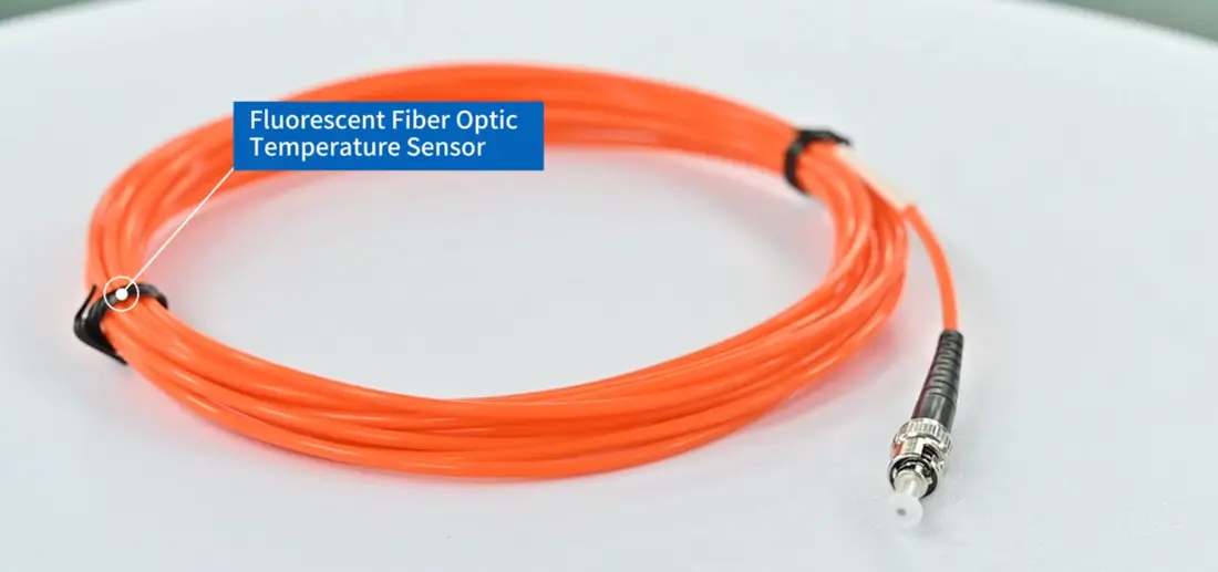
- Fiber optic thermometers measure temperature at the tip of a passive optical probe. No electrical signal wiring runs to the measured point.
- INNO’s fluorescent fiber optic temperature sensor excites a fluorescent material at the probe tip and converts the decay of the returned light into a temperature reading.
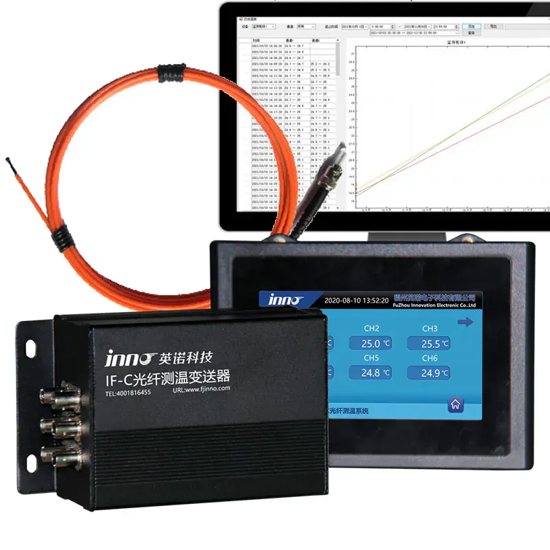
- A complete system combines probes, optical fiber or extension cable, a multi-channel measuring instrument, a local display or RS485 output, and optional monitoring software.
- Typical uses are transformer and reactor windings, switchgear connections, generator and motor stators, MRI equipment, microwave processes and high-voltage tests.
- Probe ranges reach -40 to 260 °C depending on construction, and hosts support 1 to 64 channels, so one system can cover a single point or a full multi-point installation.
What Is a Fiber Optic Thermometer?
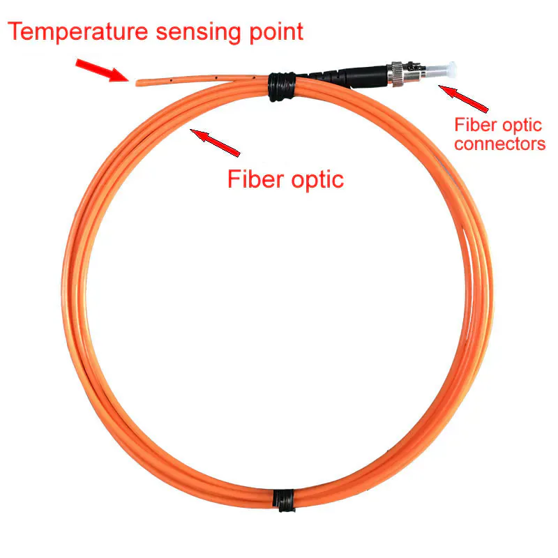
Fiber optic thermometers read temperature through an optical fiber instead of an electrical cable. Sensing material sits in a small probe tip at the measurement point, and a measuring instrument installed in a cabinet or control panel sends light down the fiber and works out the temperature from the light that comes back.
No electrical signal wiring runs to the measured point. That one property explains why engineers specify this equipment for energized windings, switchgear joints, MRI rooms and microwave cavities.
It is a contact measurement, and each probe reads one point. Ten measurement points call for ten probes and a host with at least ten channels.
Depending on the supplier, the same equipment is sold as a fiber optic temperature sensor, optical temperature sensor, temperature measurement device or temperature monitoring system. At INNO, “probe” means the sensing tip with its fiber, “host” means the temperature measurement instrument that reads it, and “fiber optic thermometer” means the whole chain from probe to data output.
How Does a Fluorescent Fiber Optic Temperature Sensor Work?
INNO builds its fluorescent fiber optic temperature sensors around fluorescence decay:
- The host sends excitation light through the fiber.
- Fluorescent material at the probe tip absorbs the light and emits fluorescence.
- The fluorescence travels back along the fiber to the host.
- The host measures how fast the fluorescence decays and converts that decay time into temperature.
Decay time changes with temperature, so the reading depends on timing rather than brightness. Bending the fiber or adding a connector reduces the returned light but does not change the decay time, which keeps the measurement valid as long as the host receives enough signal.
What Does a Complete Temperature Measurement System Include?
Probes alone give no reading. They need a compatible host, and the host needs somewhere to send its data. A complete system usually has these parts:
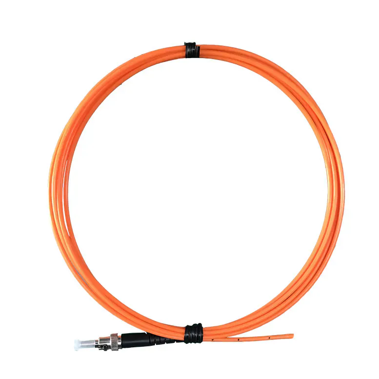
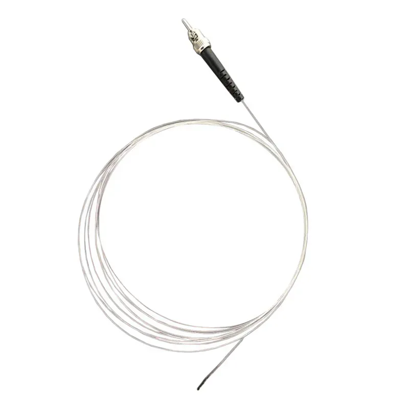
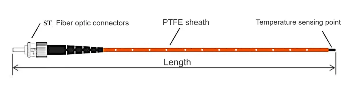
- Fiber optic temperature probes. Fluorescent tip, fiber, protective sheath and connector. The standard fluorescent probe suits general measurement points, and application-specific versions exist for windings, busbar joints, motors and MRI.
- Extension cable. When the route is longer than the probe fiber, the fiber optic extension cable adds optical length.
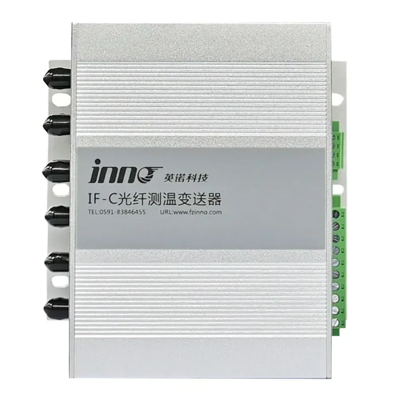
- Multi-channel measuring instrument. It excites each probe, calculates temperature and drives alarm relays, RS485 and optional analog outputs. The IF-C multi-channel transmitter is INNO’s main host family.
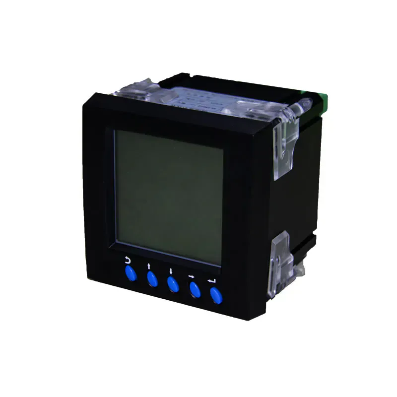
- Local display. The LCD display instrument or the display-integrated host shows temperature and alarm status at the panel.
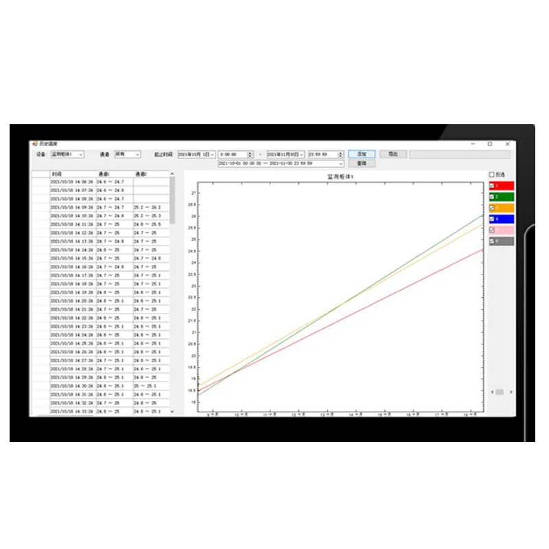
- Monitoring software. Trending, recording and remote monitoring through the monitoring software platform.
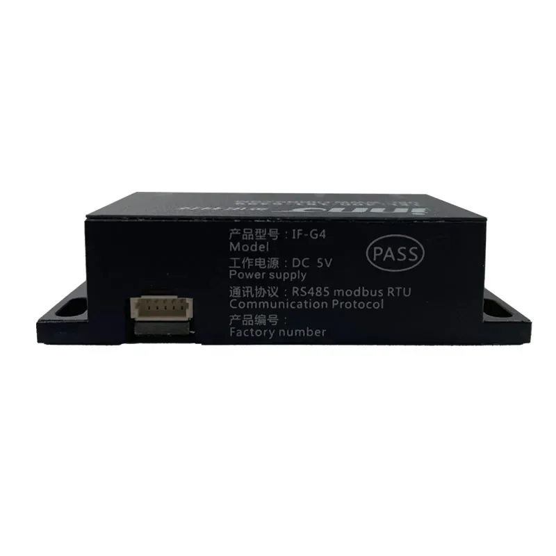
- OEM modules. Compact IF-G modules build temperature acquisition into customer equipment.
Probes connect to the host, never directly to a PLC. The host provides the industrial interface. When the whole chain is specified for one asset, INNO supplies it as a configured fiber optic temperature monitoring system.
Why Do High-Voltage and High-EMI Locations Need Optical Temperature Sensors?
- No conductive path to the measured point. Light in the fiber carries the signal, so nothing conductive connects an energized point to the electronics. Several INNO probe configurations are listed at 100 kV or above. Clearances and fiber routing inside the equipment still have to be designed properly.
- High resistance to electromagnetic interference. Metal sensor leads in strong magnetic or RF fields collect noise and create ground loops. The optical sensing path resists electromagnetic interference; the instrument and installation still require suitable engineering.
- Readings at the actual point. The value comes from where the probe sits, not from a model. For windings, that means a measured temperature to compare against indicated or calculated values.
- Small probes, quick response. Probe tips of a few millimetres fit tight spaces, and the standard probe responds in under a second.
Where Is a Fiber Optic Thermometer Used?
Power Transformer Winding Temperature Monitoring
Winding temperature decides how fast transformer insulation ages, yet the usual indication is derived from top-oil temperature and load current. Fluorescent probes placed at winding locations chosen from the thermal design report the temperature at those points directly. Installation happens during winding or overhaul, because internal access exists only then.
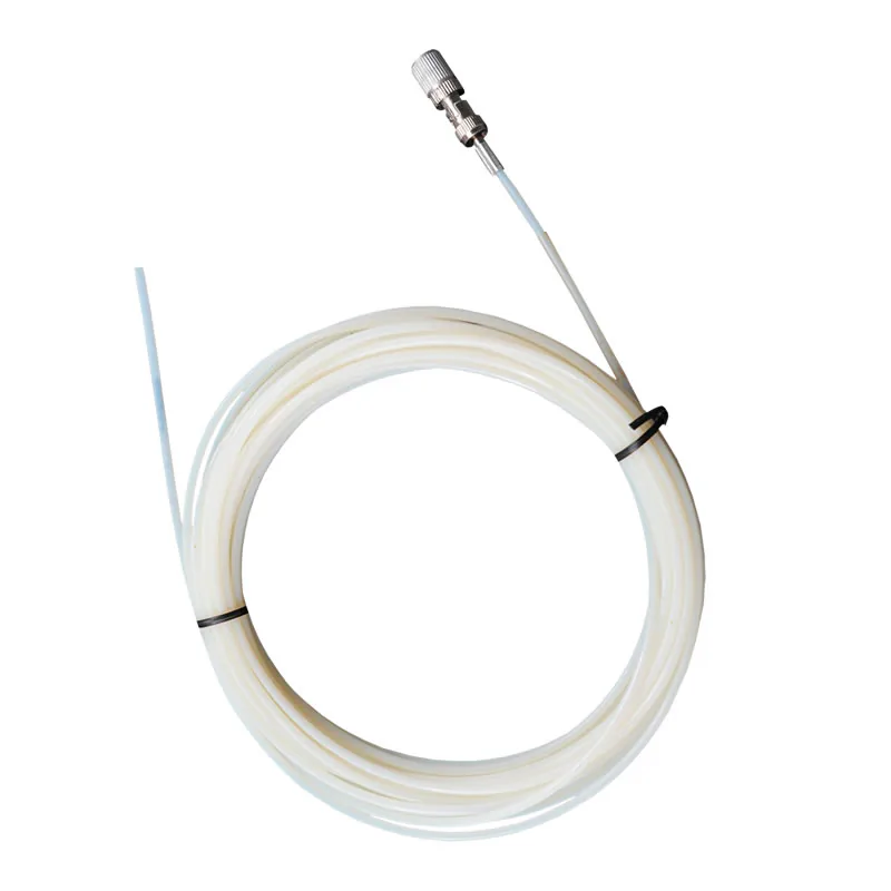
Probe construction follows the space and the mechanical risk. The thin polyimide winding probe suits embedded points with little room, the armored winding probe adds mechanical protection, and the oil-immersed transformer winding sensor is made for embedded points in oil-filled units. Fibers leave the tank through feedthroughs and flanges from INNO’s transformer installation components and run to a host in the control cabinet. A 110 kV project using this arrangement is documented in the oil-immersed transformer case study, and the full range sits under transformer temperature monitoring.
Dry-Type Transformer Temperature Monitoring
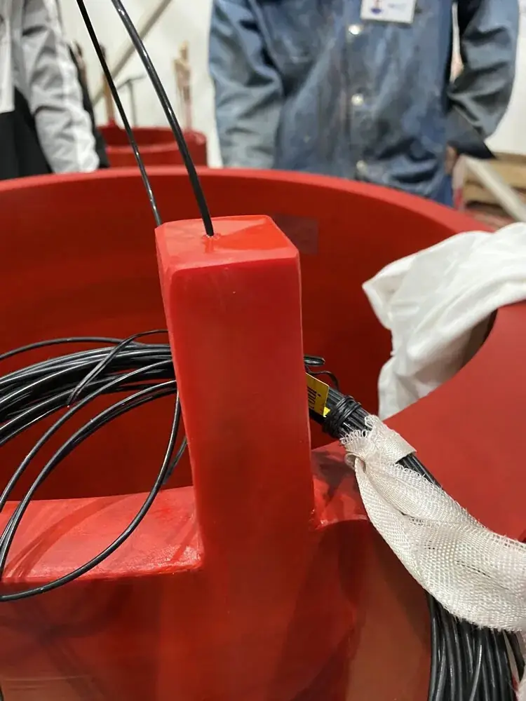
Dry-type transformers and reactors run in enclosures where winding temperature limits the load. Probes are positioned at selected winding locations, giving direct multi-point readings without conductive sensor wiring near the coils. INNO configures this as the dry-type transformer winding monitoring system, which combines optical probes, monitoring hardware, alarm logic and communication outputs. Variants exist for dry-type reactors, box-type substation transformers and rail-transit transformers.
Switchgear and Busbar Temperature Monitoring
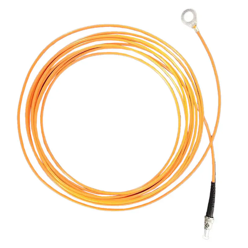
Heat in switchgear starts at joints: bolted busbar connections, contacts and cable terminations. The busbar and bolt connection probe is an O-ring style assembly that sits under the bolt, so the sensing tip is in direct contact with the connection. Fiber length is configurable from 1 to 15 m to reach the host.
Where a lineup has a defined number of joints, the IF-C nine-channel host fits when nine points are already approved. The switchgear monitoring system packages probes, alarm and relay outputs and RS485 / Modbus planning, and compact units have a dedicated ring main unit cable joint system. A hydropower installation is described in the switchgear case study, and the wider range is under switchgear temperature monitoring.
Generator and Motor Winding Temperature Monitoring
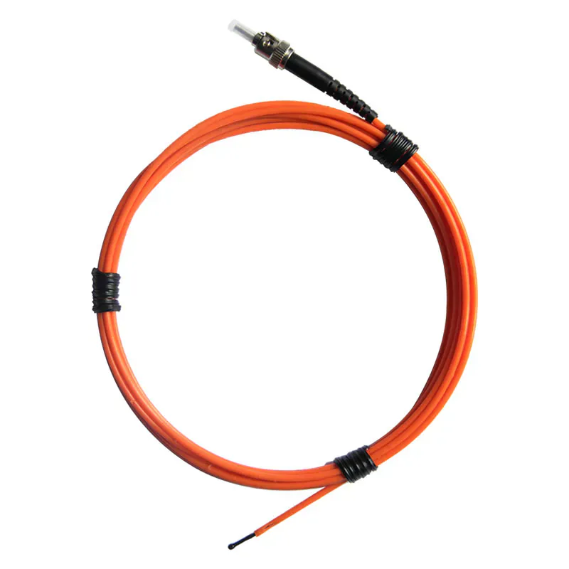
Stator windings sit in strong fields, and what matters is the temperature at chosen slots, not the frame. The motor winding probe has a quartz fluorescent tip in 2.5 or 3 mm diameter, with a configurable range up to +260 °C. Several probes spread around the stator give a multi-point picture through one host, as in the generator stator winding case. For complete machines, INNO offers the generator set monitoring system, and the motor and generator application covers selected winding points on rotating machines.
MRI Temperature Measurement
Metal leads and conductive sensors do not belong inside an MRI bore. The MRI and RF probe is listed for 20 to 50 °C at ±0.3 °C, with a 1.5 mm tip and 5 m of fiber, so the host stays outside the magnetic field while the tip measures inside it. The MRI-compatible measurement arrangement shows how this is set up, and MRI temperature monitoring lists related medical and laboratory uses.
Microwave and RF Equipment Temperature Measurement
Microwave heating puts conventional sensors inside the field they are trying to measure. Optical probes can sit in the process zone while the host stays outside. INNO configures this as the microwave EMI-immune monitoring system. Processes running outside the standard range can use the high- and low-temperature probe, and further applications are listed under microwave temperature monitoring.
High-Voltage Temperature Measurement
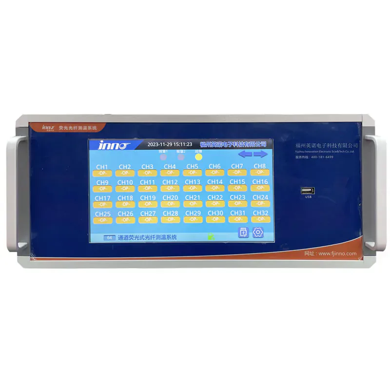
Type tests, dielectric tests and impulse tests need temperatures from energized objects, often at many points at once. Isolated probes combined with a multi-channel host cover that. The 32-channel test equipment system serves laboratory rigs, and high-voltage temperature monitoring covers test benches and selected points on test objects.
Fiber Optic Temperature Monitoring Solutions
Different measurement jobs call for different combinations of the same building blocks: fluorescent fiber optic sensors, probes, extension cables, measuring hosts, monitoring software and communication interfaces. These are the combinations INNO configures most.
Direct Temperature Monitoring of Transformer Winding Hot Spots
Insulation ages where the winding runs hottest. This solution places fluorescent probes at winding locations picked from the thermal design, so the reading comes from the point itself rather than from a calculation. One limit has to be stated plainly: a point probe reads only where it is installed, so placement is agreed with the transformer designer and normally done before final assembly or during an overhaul when the winding is accessible.
Typical equipment is a polyimide, armored or winding tube probe, depending on space and mechanical protection, fibers routed out of the tank through feedthroughs and flanges, and a host in the control cabinet. That host is either an IF-C transmitter or the oil-immersed transformer monitoring system, which covers 1 to 18 channels with RS485 / Modbus and an optional 4–20 mA output. Many projects compare the direct readings with top-oil and calculated temperatures that are already available. The method is set out under direct hot-spot monitoring.
Multi-Point Temperature Monitoring for Electrical Equipment
Each probe takes one channel, so multi-point temperature monitoring comes down to matching channel count to the point list and grouping channels by equipment. Three typical cases:
- A switchgear lineup with nine monitored joints fits a nine-channel host.
- A thermal test rig with up to 32 points fits the 32-channel test equipment system.
- Large industrial projects can use the 64-channel monitoring system.
Spare channels cost little at order stage and are awkward to add later, so most point lists are worth reviewing with some headroom.
Electrically Isolated Measurement in High-Voltage Environments
Test laboratories and energized equipment share one problem: conventional sensors need wiring that can float to high potential or pick up noise. Here the passive optical probe stays at the measurement point and the host sits in a safe, reviewed location. Depending on the probe and instrument, typical accuracy is ±0.5 to ±1.0 °C within the standard -40 to +260 °C range.
Specification starts with the voltage level, the type and severity of the EMI or RF source, the fiber route to the host and the space available for it. Those answers decide probe construction and fiber length. INNO describes the complete approach under high-voltage equipment temperature monitoring.
PLC and SCADA Temperature Monitoring Integration
Hosts turn each probe channel into temperature data and relay alarms. Getting that into plant controls is mostly mapping work: RS485 / Modbus registers, optional 4–20 mA signals, alarm thresholds, tag names and channel grouping by equipment. INNO reviews the point list against the existing PLC, DCS or SCADA platform, and the panel and enclosure arrangement can be adapted to the cabinet.
Where operators want trends, the monitoring software adds recording and remote monitoring. Temperature points added to existing installations are handled the same way, with retrofit and legacy system integration reviewed against the control system already in place. The PLC and SCADA integration process runs from review through configuration to connectivity checks before go-live.
Customized OEM Temperature Sensing Solutions
Equipment builders usually need less than a complete system: a probe made to fit their mechanical layout and a compact module that reports over RS485. INNO supplies IF-G modules in one-, three- and four-channel versions, and develops custom OEM measurement modules around channel count, interfaces and mechanical constraints. The four-channel IF-G4, for example, runs on DC 5 V and updates temperature every 300 ms.
Probe diameter, sheath material, fiber length and connectors can also be adapted, as can labeling, documentation and test records for production programs. Projects follow four steps: application review, definition of the sensing package, interface validation and delivery. The scope is described under custom and OEM temperature sensing.
Which INNO Probes, Instruments and Systems Fit Which Job?
Fiber Optic Temperature Probes
Probe choice follows the measurement point rather than the equipment name. Representative configurations:
| Probe | Typical point | Listed range | Listed details |
|---|---|---|---|
| Standard fluorescent probe | General point in HV, EMI, RF or industrial equipment | -40 to 260 °C | 2–3 mm diameter, 0–20 m fiber, ST connector |
| Busbar and bolt connection probe | Busbar joints and bolted connections | -40 to +260 °C | Copper O-ring assembly, 1–15 m fiber |
| Polyimide winding probe | Embedded transformer winding point | -40 to +260 °C | 2.5 mm sensing tip |
| Oil-immersed winding sensor | Embedded winding in oil-filled units | -40 to +260 °C | ±1 °C, 100 kV listed, 3 m polyimide fiber with PTFE sheath |
| Motor winding probe | Stator winding in motors and generators | -40 to +260 °C configurable | Quartz tip, 2.5 or 3 mm |
| MRI and RF probe | MRI, RF and strong magnetic fields | 20 to 50 °C | ±0.3 °C, 1.5 mm tip, 5 m fiber |
The winding tube sensor covers points that need a protective tube, and its FC/APC connector differs from the ST connector on the standard probe, so connector and host must be matched. Listed values reflect current configurations and can vary by probe version.
Multi-Channel Temperature Monitoring Instruments
The host decides how many points you can read, how alarms trigger and how data leaves the cabinet.
| Instrument | Channels | Role and listed details |
|---|---|---|
| IF-C multi-channel transmitter | 1–64 | Configurable family. -40 to +260 °C, ±1 °C standard, 0.1 °C resolution, dual RS485 / Modbus, optional 4–20 or 0–20 mA, two alarm relays (5 A / 250 VAC), AC/DC 220 V standard. |
| IF-C nine-channel host | 9 | Fixed configuration for panels with an approved nine-point schedule. RS485 / Modbus, optional 4–20 mA. |
| Display-integrated host and LCD display instrument | By configuration | Local temperature and alarm display for control panels. |
| IF-G4 OEM module | 4 | Embedded acquisition for customer equipment. DC 5 V, RS485 communication. |
Smaller point counts are covered by the six-channel host, the four-channel device and the three-channel transmitter.
Complete Fiber Optic Temperature Monitoring Systems
When probes, fiber, host and outputs are specified together for one asset, a configured system saves compatibility checks. INNO lists systems for oil-immersed and dry-type transformers, switchgear, generator sets, test equipment and semiconductor equipment, among others. The switchgear system is a representative example, with configurable channels and alarm and relay outputs.
How Do You Select a Fiber Optic Temperature Measurement System?
Measuring Range
Write down the lowest, normal and highest temperature at the sensing point, including short excursions. Most probes cover -40 to +260 °C, and projects beyond the standard range use the high-temperature configuration. The temperature range of a fiber optic temperature sensor depends on probe construction as well as the number printed on the datasheet.
Number of Measurement Points and Channels
Count points, not machines. One probe uses one channel. Order the host after the point schedule is approved, and leave some spare capacity.
Probe Type
Match the probe to the point and its mechanical environment: polyimide for embedded windings, armored or tube construction where protection is needed, the O-ring probe for bolted joints, quartz-tip probes for motor windings. Choosing a fiber optic temperature sensor starts from the physical location, not the catalogue.
Fiber Length
Measure the real route from probe to host, including feedthroughs and installation slack. Scaling it off a general arrangement drawing is the usual cause of wrong lengths. Standard probes list 0 to 20 m, and an extension cable covers longer runs. A fiber length plan per probe avoids rework later.
Display Functions
Decide who needs to read temperatures and where. If the control room already shows everything over Modbus, a host without display is enough. If maintenance staff read at the panel, choose the LCD display instrument or display-integrated host. If trends and records matter, add the software platform.
Communication Interfaces
The IF-C transmitter provides dual RS485 with Modbus, two alarm relays and optional analog outputs. Confirm the register map and I/O list with the control-system team before ordering, and send any requirement beyond these interfaces so INNO can confirm what is available.
For a quote review, the most useful information is the equipment drawing, the list of measurement points, the temperature range, the fiber route, the display and alarm needs, and the interface and power supply. Probes and hosts from different sources are not automatically interchangeable, because sensing method, connector and instrument must match.
What Should You Look for in a Fiber Optic Temperature Sensor Manufacturer?
Engineering capability. A good supplier reviews your drawing before quoting. INNO starts with an application and requirement review covering measurement points, temperature range, channel quantity, probe type, fiber length, communication and installation, and only then configures products.
Production experience. INNO has worked on point fiber optic sensing since 2011. Probe assembly, optical fiber preparation, instrument electronics and final inspection are handled in dedicated workshops, and each configured unit goes through calibration and functional testing before shipment.
Product development and customization. Probe structure, fiber length, connectors, channel count, interfaces and enclosures can be adapted. Equipment makers can go further with OEM modules and custom assemblies.
Documented qualifications. INNO holds ISO 9001, ISO 14001, ISO 27001 and ISO 45001 certificates, CE EMC and CE LVD documents and a RoHS report. Selected inspection reports include a power frequency withstand voltage test report for the fluorescent fiber optic temperature sensor, and UL and other market-specific requirements can be discussed on request. Details are on the INNO company page.
Technical support and response. Customers deal directly with application engineers, from selection through commissioning. Datasheets, wiring information, communication documents and test records are prepared for the project.
Discuss Your Measurement Requirement with INNO
If you already know what needs to be measured, send the equipment drawing, the measurement points, the temperature range, the fiber route and the interface you need. INNO engineers will propose probes, a host and a configuration that fit. Reach us at info@innofj.com, on WhatsApp +86 135 9907 0393, or through the contact page.