
Rail-Transit Transformer Winding Fiber Optic Temperature Monitoring System
An application-specific optical temperature monitoring configuration for selected winding points in rail-transit transformer projects.
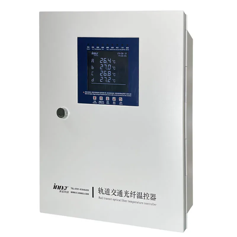
RAIL-TRANSIT TRANSFORMER WINDING MONITORING CONFIGURATION
Plan direct winding temperature points and a compatible monitoring architecture for a rail-transit transformer application.
This option is intended for projects where plan direct winding temperature points and a compatible monitoring architecture for a rail-transit transformer application.
A rail-transit application package rather than a generic transformer probe or universal transmitter.
- Rail-transit transformers
- Coordinate probe installation, protected fiber routing and host placement with the transformer and vehicle project.
Product Overview
Rail-Transit Transformer Winding Fiber Optic Temperature Monitoring System is designed for a defined role in a fiber optic temperature measurement project. An application-specific optical temperature monitoring configuration for selected winding points in rail-transit transformer projects.
The final configuration should be selected from the measurement target, installation conditions and the components required around it. It should not be treated as a substitute for the other compatible parts of the optical measurement path.
APPLICATION CONTEXT
Rail-Transit Transformer Winding Fiber Optic Temperature Monitoring System Selection Context
The equipment and temperature points determine whether this product is appropriate. A project review should establish the practical function it will perform before the configuration is finalized.
- Transformer type and winding locations
- Rail-transit installation constraints
CONFIGURATION REVIEW
Configuring Rail-Transit Transformer Winding Fiber Optic Temperature Monitoring System
The selection process should connect the product to its installation route, compatible hardware and the way temperature information will be used.
- Point quantity and channel count
- Alarm and communication requirements
PRODUCT DATA
Technical Specifications
Select the final configuration around the equipment design and required measurement points.
APPLICATION FIT
Typical Project Uses
Selection should start with the actual application and the role this product plays in the complete optical measurement path.
Rail-transit transformers
Review this product’s role, installation method and related components against the actual application.
Traction power equipment
Review this product’s role, installation method and related components against the actual application.
Transformer winding hot spots
Review this product’s role, installation method and related components against the actual application.
Electrically demanding rolling-stock assets
Review this product’s role, installation method and related components against the actual application.
BUYER QUESTIONS
Frequently Asked Questions
What is the role of this rail-transit transformer winding monitoring configuration?
It is used to address a specific fiber optic temperature measurement requirement. The final configuration should be checked against the application, connected probes and required outputs.
Does it include every component needed for measurement?
The final arrangement depends on the product role. Compatible probes, optical connections, power, enclosure integration and data interfaces should be confirmed for the project.
What information is needed for a configuration review?
Share the measurement target, installation environment, required number of points and any display, alarm or communication requirements. Transformer type and winding locations should also be confirmed.
RELATED PRODUCTS
Related Components and Systems
These products serve different roles in the same optical temperature-measurement path.
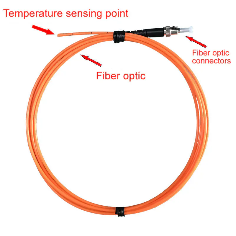
Standard Fluorescent Fiber Optic Temperature Probe
Fluorescence-based point temperature sensor for electrically isolated measurement in high-voltage, EMI, RF, microwave and other demanding environments.
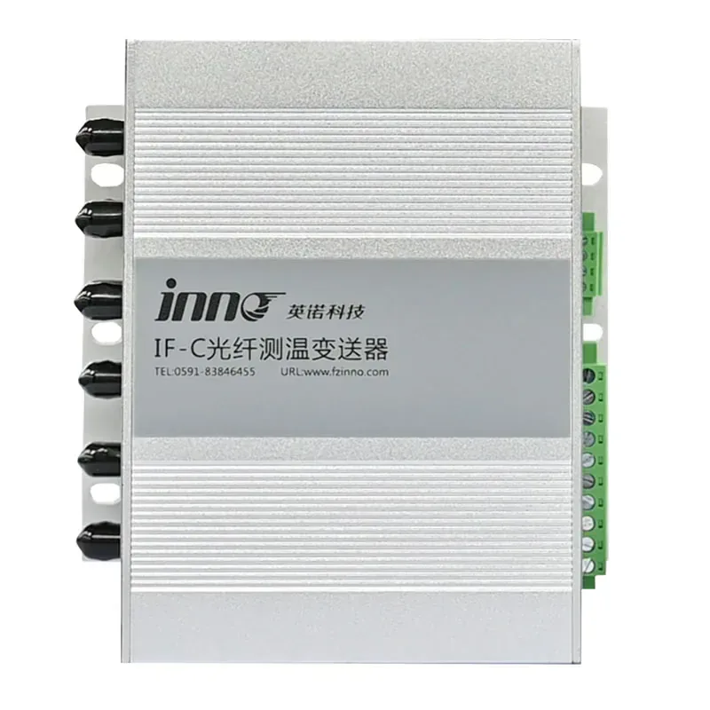
IF-C Multi-Channel Fiber Optic Temperature Transmitter
A configurable multi-channel host that converts signals from separate fluorescence fiber optic probes into temperature data, relay alarms, RS485 communication, and optional analog outputs.
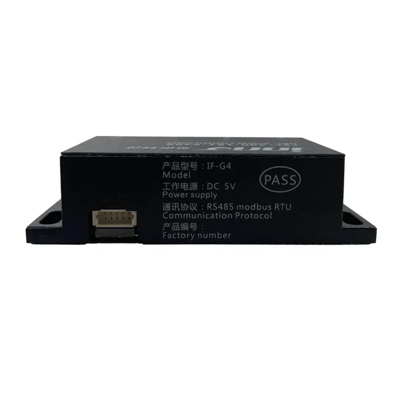
IF-G4 Four-Channel OEM Fiber Optic Temperature Module
A compact four-channel optical temperature acquisition module for integration into industrial equipment, test platforms, and OEM monitoring assemblies.
PRODUCT CONFIGURATION REVIEW
Plan the Right Product Configuration
Tell us how this rail-transit transformer winding fiber optic temperature monitoring system will be used. INNO can review the measurement point, installation route, channel requirements and system interface against the selected product.
- Measurement target: Rail-transit transformers
- Installation method: Coordinate probe installation, protected fiber routing and host placement with the transformer and vehicle project.
- Product selection: Transformer type and winding locations
- System requirement: Alarm and communication requirements
Include the operating temperature range, number of measurement points and required communication or alarm outputs where applicable.