
Oil-Immersed Transformer Winding Fiber Optic Temperature Sensor
A passive fluorescence fiber optic temperature sensor for selected oil-immersed transformer winding measurement points and reviewed internal routing.
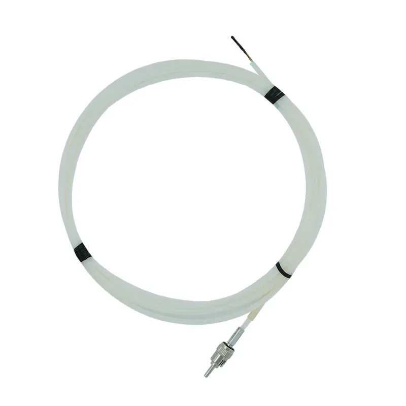
OIL-IMMERSED TRANSFORMER WINDING OPTICAL TEMPERATURE SENSOR
Place a passive optical temperature point within the transformer winding assembly and route it to a compatible host without introducing a conductive sensing path.
This option is intended for projects where place a passive optical sensing point at a selected internal transformer winding location while preserving electrical isolation.
This product is the internal sensing element. It requires a compatible fluorescence monitoring host and any required tank-boundary routing components to form a complete measurement system.
- Oil-immersed transformer windings
- Approve the sensing-tip location, 3 m or custom fiber length, polyimide fiber, PTFE sheath and protected route as part of the transformer build.
Oil-Immersed Transformer Winding Sensor Overview
This passive fluorescence fiber optic temperature sensor is intended for selected internal winding and hot-spot locations in oil-immersed transformers. The configuration uses polyimide fiber with a PTFE sheath and provides an optical measurement path to a compatible monitoring host.
The source lists a -40 °C to +260 °C temperature range, 0.1 °C resolution, ±1 °C measurement accuracy, a standard 3 m length with custom length available and 100 kV high-voltage resistance. Final construction and installation details must be checked against the transformer design.
The sensor is not a complete monitor. A compatible fluorescence transmitter or monitoring host, suitable optical connections and any required flange or penetrator assembly are selected separately.
INSTALLATION ROLE
Plan the Sensing Point Before Final Winding Assembly
The probe position and protected fiber route should be application-specific while the transformer winding and insulation structure are still accessible.
- Approve the actual thermal point to be measured.
- Protect the fiber path through the winding and insulation arrangement.
- Define the transition from the internal probe to the external monitoring host.
SYSTEM COMPATIBILITY
Complete the Optical Measurement Path
The sensor must be paired with compatible optical routing components and a fluorescence signal-processing instrument.
- Confirm fiber length and connector arrangement.
- Select tank-boundary components when the route leaves an oil-filled enclosure.
- Match sensor quantity to the required host channel count.
PRODUCT DATA
Technical Specifications
Select the final configuration around the equipment design and required measurement points.
APPLICATION FIT
Typical Project Uses
Selection should start with the actual application and the role this product plays in the complete optical measurement path.
Oil-immersed transformer windings
Review this product’s role, installation method and related components against the actual application.
Internal transformer hot spots
Review this product’s role, installation method and related components against the actual application.
Transformer manufacturing
Review this product’s role, installation method and related components against the actual application.
High-voltage insulation structures
Review this product’s role, installation method and related components against the actual application.
BUYER QUESTIONS
Frequently Asked Questions
Is this sensor a complete transformer temperature monitoring system?
No. It is the passive internal sensing element and requires a compatible fluorescence monitoring host plus the optical routing components required by the transformer design.
What standard fiber length is listed?
The collected product source lists a 3 m standard length and states that custom lengths are available. Confirm the final route before ordering.
Can the sensor be installed after the transformer winding is complete?
Installation feasibility depends on the winding construction and access. The sensing position and protected fiber route should normally be reviewed as part of the transformer design and assembly plan.
How does the sensor pass through the transformer tank boundary?
A reviewed penetrator and flange arrangement may be used where the optical path crosses the tank boundary. The exact assembly depends on tank geometry and sealing requirements.
RELATED PRODUCTS
Related Components and Systems
These products serve different roles in the same optical temperature-measurement path.
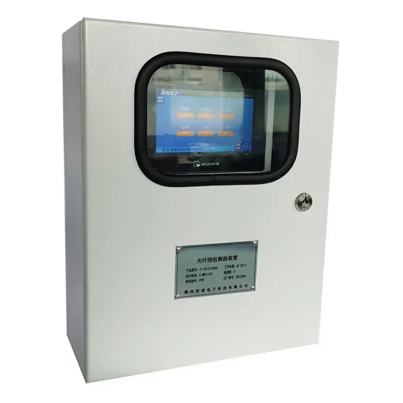
Oil-Immersed Transformer Fiber Optic Temperature Monitoring System
A configured fiber optic temperature monitoring system for selected internal temperature points in oil-immersed transformer projects.
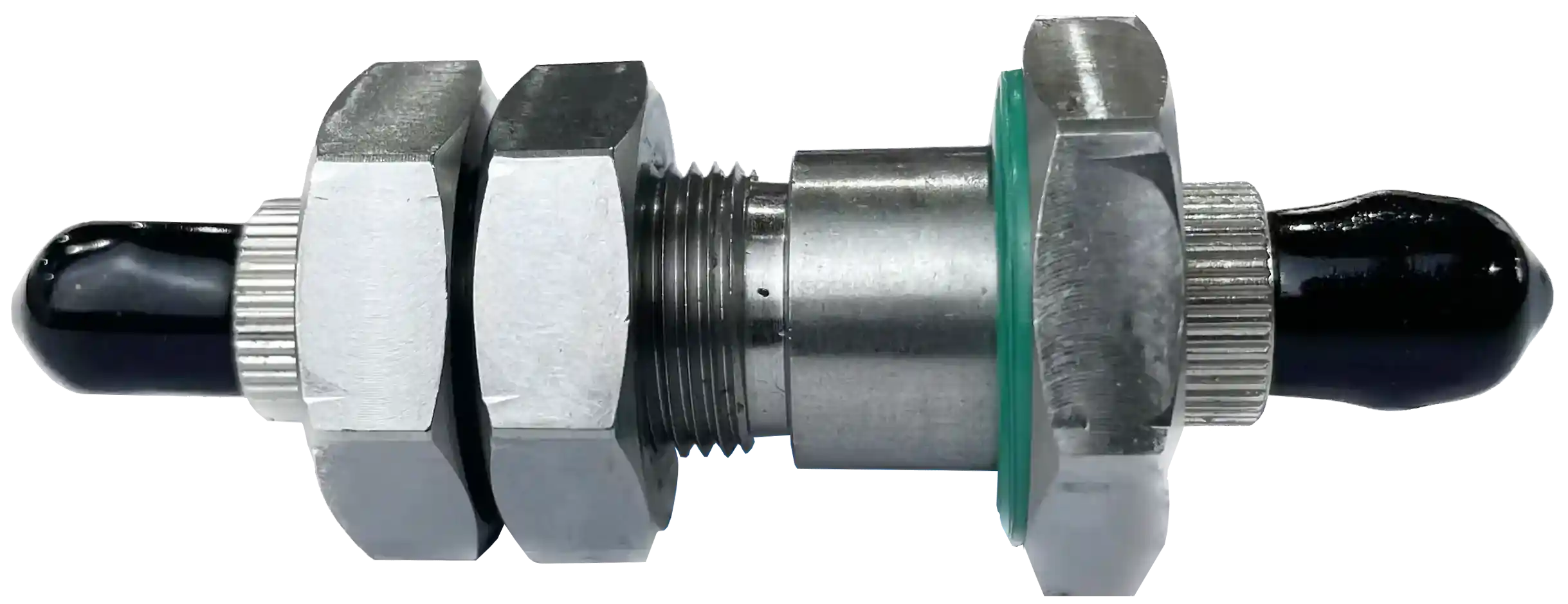
Transformer Fiber Optic Penetrator
A 316 stainless-steel optical penetrator that transitions between an internal transformer sensing probe and external optical fiber at the tank boundary.
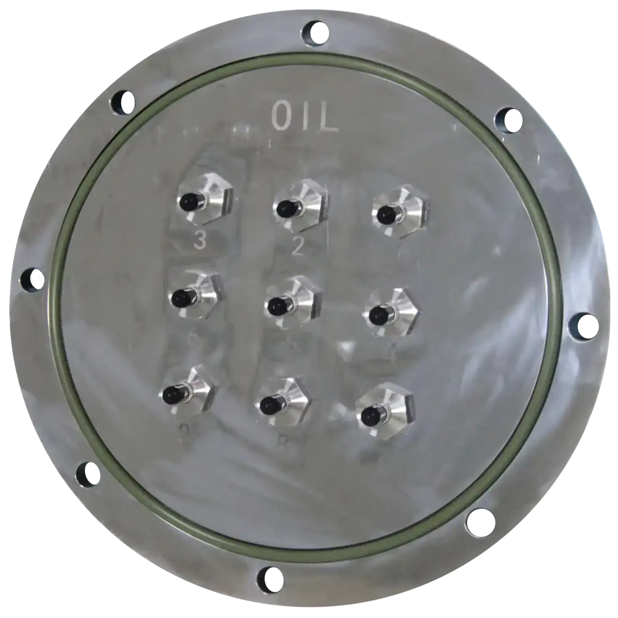
Transformer Tank Flange Plate
A 316 stainless-steel flange plate for fixing 1–16 optical penetrators to an oil-immersed transformer tank wall together with a matching flange ring.
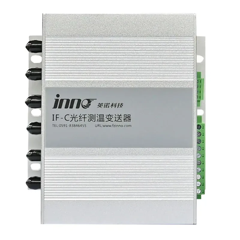
IF-C Multi-Channel Fiber Optic Temperature Transmitter
A configurable multi-channel host that converts signals from separate fluorescence fiber optic probes into temperature data, relay alarms, RS485 communication, and optional analog outputs.
PRODUCT CONFIGURATION REVIEW
Plan the Right Product Configuration
Tell us how this oil immersed transformer winding fiber optic temperature sensor will be used. INNO can review the measurement point, installation route, channel requirements and system interface against the selected product.
- Measurement target: Oil-immersed transformer windings
- Installation method: Approve the sensing-tip location, 3 m or custom fiber length, polyimide fiber, PTFE sheath and protected route as part of the transformer build.
- Product selection: Approved winding measurement location
- System requirement: Compatible host and total channel count
Include the operating temperature range, number of measurement points and required communication or alarm outputs where applicable.