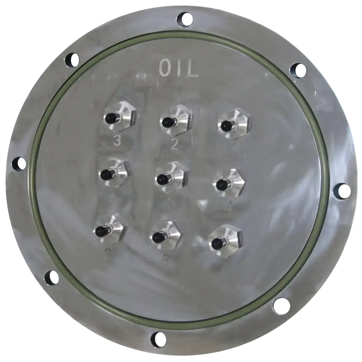
Transformer Installation Components
Transformer Tank Flange Plate
A 316 stainless-steel flange plate for fixing 1–16 optical penetrators to an oil-immersed transformer tank wall together with a matching flange ring.
 info@innofj.comContact Engineering
INNO PRODUCT CATEGORY
Compare flange plates, flange rings, optical penetrators and protective covers for reviewed oil-immersed transformer winding sensor installations.
CATEGORY OVERVIEW
An oil-immersed transformer winding sensor needs a reviewed path from the internal sensing point to the external monitoring instrument. The tank-wall assembly may include a welded flange ring, removable flange plate, individual optical penetrators and an external protective cover.
These are installation components, not temperature sensors or monitoring hosts. Their dimensions, quantity, sealing arrangement and tank interface must be coordinated with the transformer design.
TRANSFORMER TANK INTERFACES
Compare penetrators, flange components and protective hardware by their role in routing sensor fibers through the transformer tank boundary.
Transformer Installation Components
A 316 stainless-steel flange plate for fixing 1–16 optical penetrators to an oil-immersed transformer tank wall together with a matching flange ring.
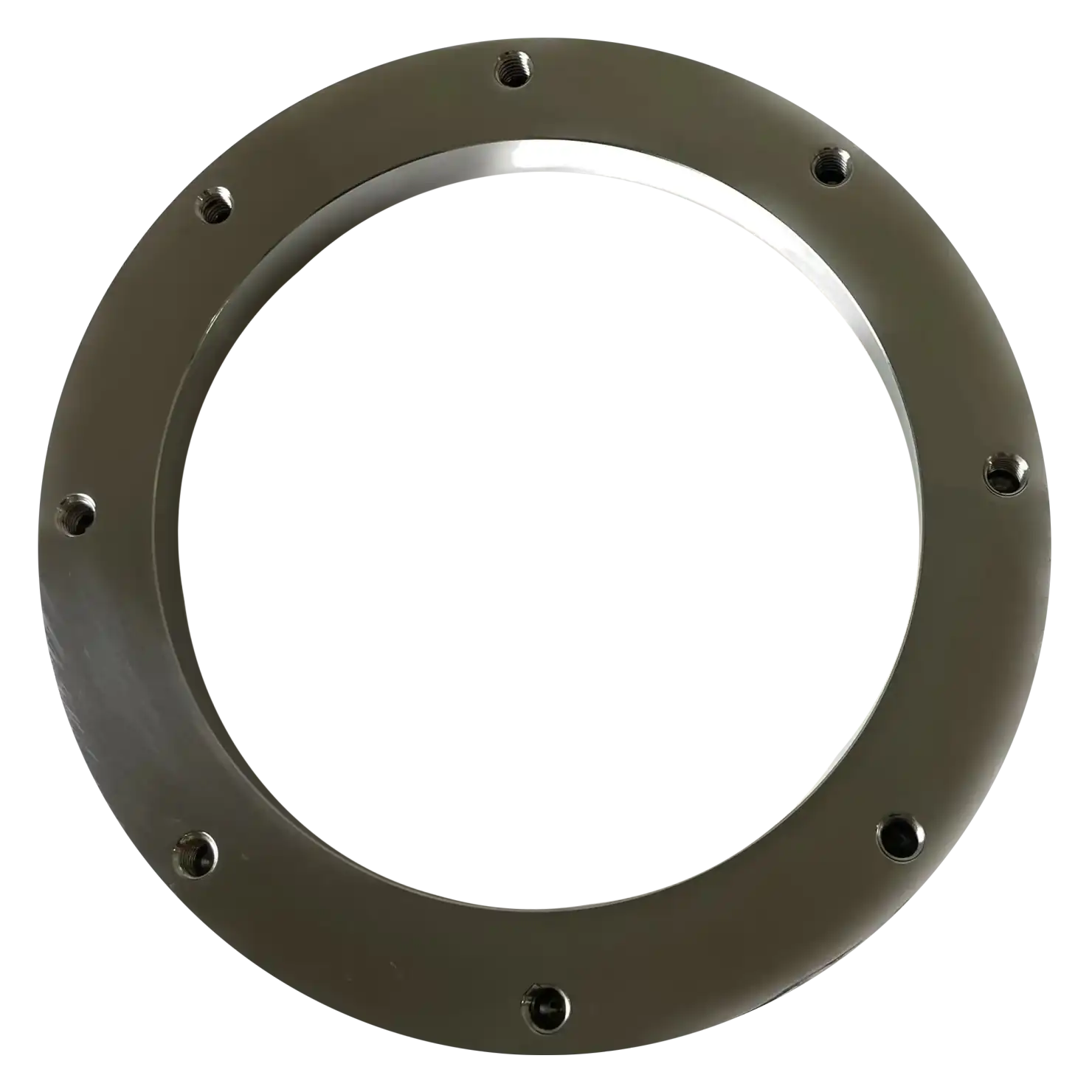
Transformer Installation Components
A 316 stainless-steel flange ring welded to the inside wall of an oil-immersed transformer tank to provide the matching interface for the external flange plate.
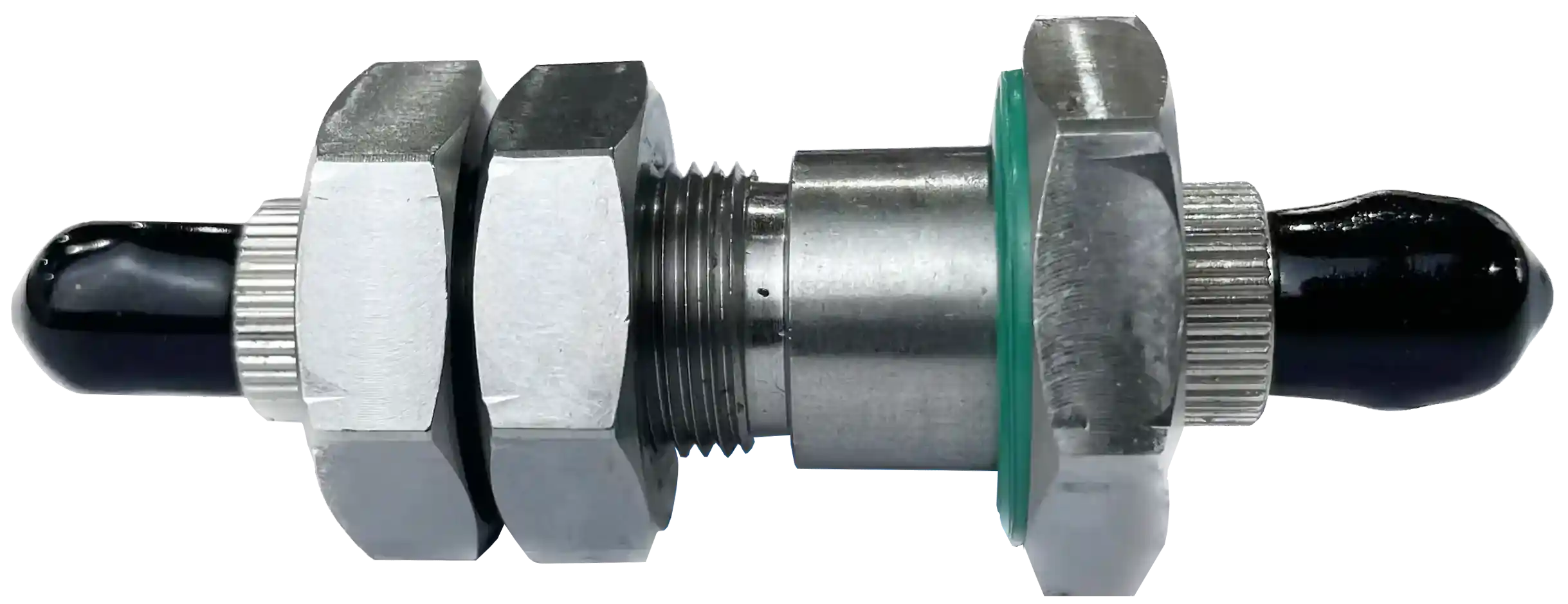
Transformer Installation Components
A 316 stainless-steel optical penetrator that transitions between an internal transformer sensing probe and external optical fiber at the tank boundary.
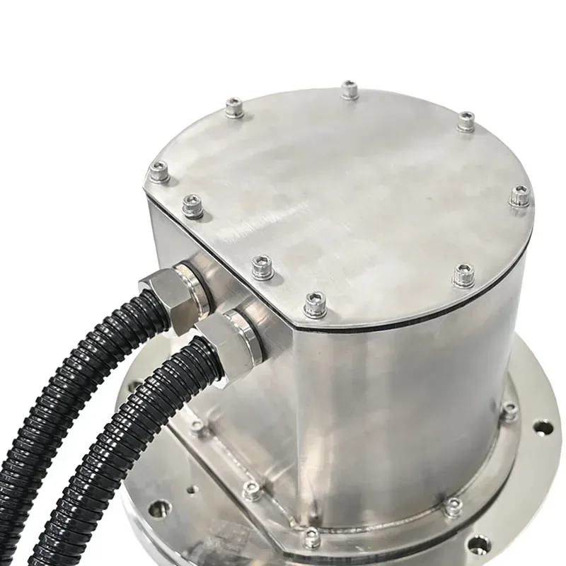
Transformer Installation Components
A 304 stainless-steel protective cover fitted over the transformer flange assembly to protect penetrators and external optical extension cables from mechanical damage and weather exposure.
ASSEMBLY PLANNING
Plan the complete boundary assembly around the transformer tank, probe count and external fiber route.
TRANSFORMER INSTALLATION SUPPORT
Share the transformer type, planned sensing points, penetrator quantity and tank-wall arrangement for review.
Discuss Your Fiber Optic Temperature Project
Get product selection and application support directly from INNO.