
Oil-Immersed Transformer Fiber Optic Temperature Monitoring System
A configured fiber optic temperature monitoring system for selected internal temperature points in oil-immersed transformer projects.
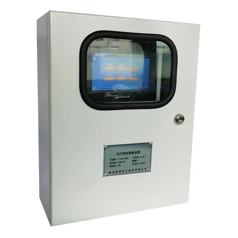
OIL-IMMERSED TRANSFORMER TEMPERATURE MONITORING SYSTEM
Define the complete optical measurement path from internal transformer hot spots to monitored temperature data, alarms and plant integration.
It provides a project-level route from reviewed internal transformer measurement points to a selected monitoring host, instead of treating a probe or transmitter by itself as a complete solution.
This is a configured oil-immersed transformer monitoring system. Individual winding probes, feedthroughs, flanges and the monitoring host are selected separately to suit the actual transformer construction.
- Oil-immersed transformers
- Coordinate probe positions, tank-boundary routing components, channel count and monitoring outputs with the transformer build and operating plan.
Product Overview
This oil-immersed transformer fiber optic temperature monitoring system is configured around selected internal winding and hot-spot locations. It combines compatible passive fluorescence probes, the required optical routing path, a monitoring host and the agreed alarm or communication functions into one reviewed measurement architecture.
The system is not a single fixed device. Probe construction is selected for each measurement location, while cable flanges, flange rings, feedthroughs or protective covers are considered wherever the transformer boundary, cable route or mechanical environment requires them. The host channel count follows the approved measurement-point plan rather than a generic product label.
For projects requiring plant integration, the monitoring arrangement can be planned around the required local display, alarm contacts, RS485 or Modbus data interface and any approved supervisory-system requirements. Final values, connectors, mechanical interfaces and outputs remain subject to the transformer and project review.
CUSTOM SYSTEM ARCHITECTURE
From Internal Winding Point to Usable Monitoring Data
A reliable transformer temperature project begins with the actual thermal location, then carries that measurement through an optical and monitoring path that has been checked as a whole.
- Select the sensing point and probe construction for the transformer winding.
- Review the optical cable route through the transformer boundary and toward the host.
- Match monitoring channels, alarm functions and communication to the operating plan.
ROUTING AND INTEGRATION
Selecting Boundary Components and System Interfaces
Mechanical transition components should be selected alongside the probe and cable route, not added as an afterthought once the transformer installation is fixed.
- Use a application-specific flange, flange ring or feedthrough where the cable crosses an equipment boundary.
- Add protective cover arrangements where the installed sensor assembly needs mechanical protection.
- Confirm the final host, display, alarms and RS485 or Modbus integration with the project team.
PRODUCT DATA
Technical Specifications
Select the final configuration around the equipment design and required measurement points.
APPLICATION FIT
Typical Project Uses
Focuses on the system architecture needed to take an internal winding temperature point through to local or supervisory monitoring.
Oil-immersed transformers
Review this product’s role, installation method and related components against the actual application.
Winding hot spots
Review this product’s role, installation method and related components against the actual application.
Utility substations
Review this product’s role, installation method and related components against the actual application.
Transformer condition monitoring
Review this product’s role, installation method and related components against the actual application.
BUYER QUESTIONS
Frequently Asked Questions
Is this a complete off-the-shelf transformer monitoring unit?
It is a configured system. The probe locations, optical routing components, host channels and outputs are selected around the actual oil-immersed transformer project.
Why are flanges and feedthroughs considered in the system design?
They can form part of the reviewed mechanical transition where a compatible optical sensor path passes through an equipment boundary. The exact component depends on the installation geometry and environmental requirements.
Can the system provide local alarms and plant communication?
The selected host and integration plan can be reviewed around local display, alarm contacts and required RS485 or Modbus communication. Confirm final functions for the project.
Does every transformer use the same probe construction?
No. The internal measurement point, winding construction, installation route and mechanical protection requirement determine the appropriate compatible probe and accessory arrangement.
RELATED PRODUCTS
Related Components and Systems
These products serve different roles in the same optical temperature-measurement path.
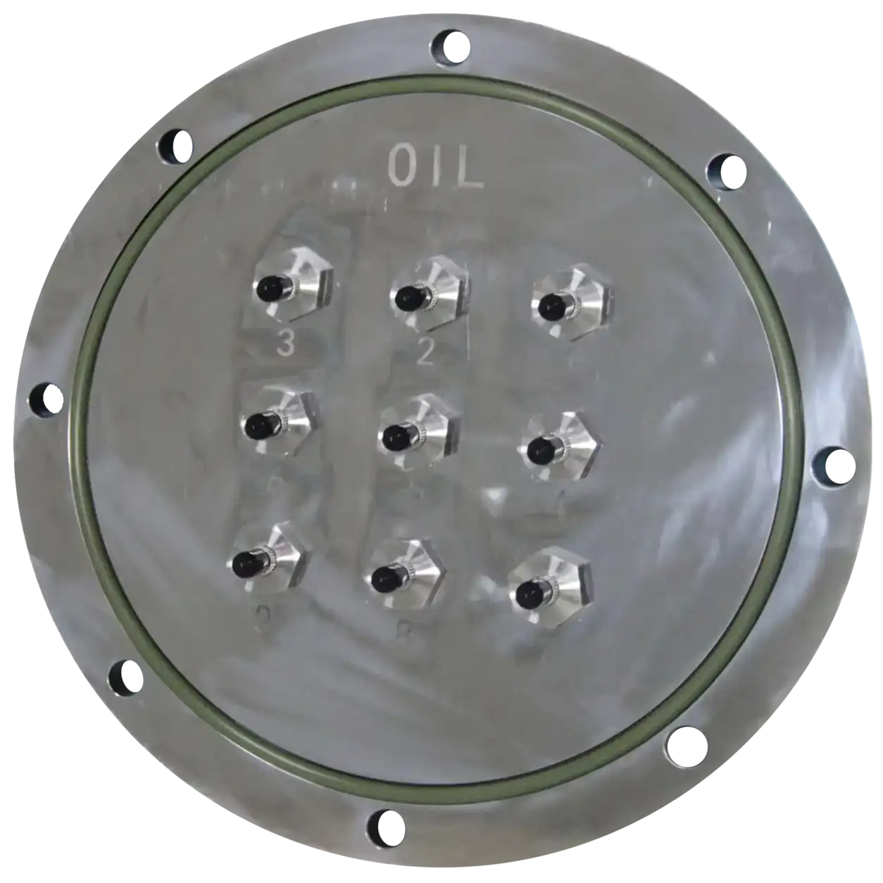
Transformer Tank Flange Plate
A 316 stainless-steel flange plate for fixing 1–16 optical penetrators to an oil-immersed transformer tank wall together with a matching flange ring.
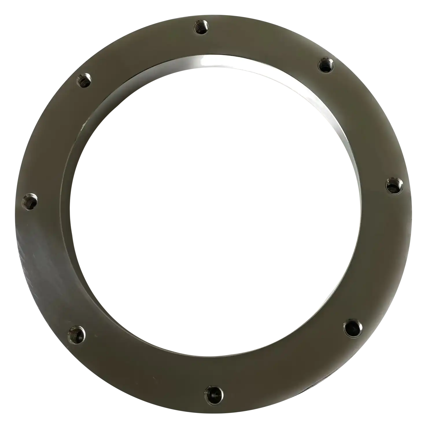
Transformer Tank Flange Ring
A 316 stainless-steel flange ring welded to the inside wall of an oil-immersed transformer tank to provide the matching interface for the external flange plate.
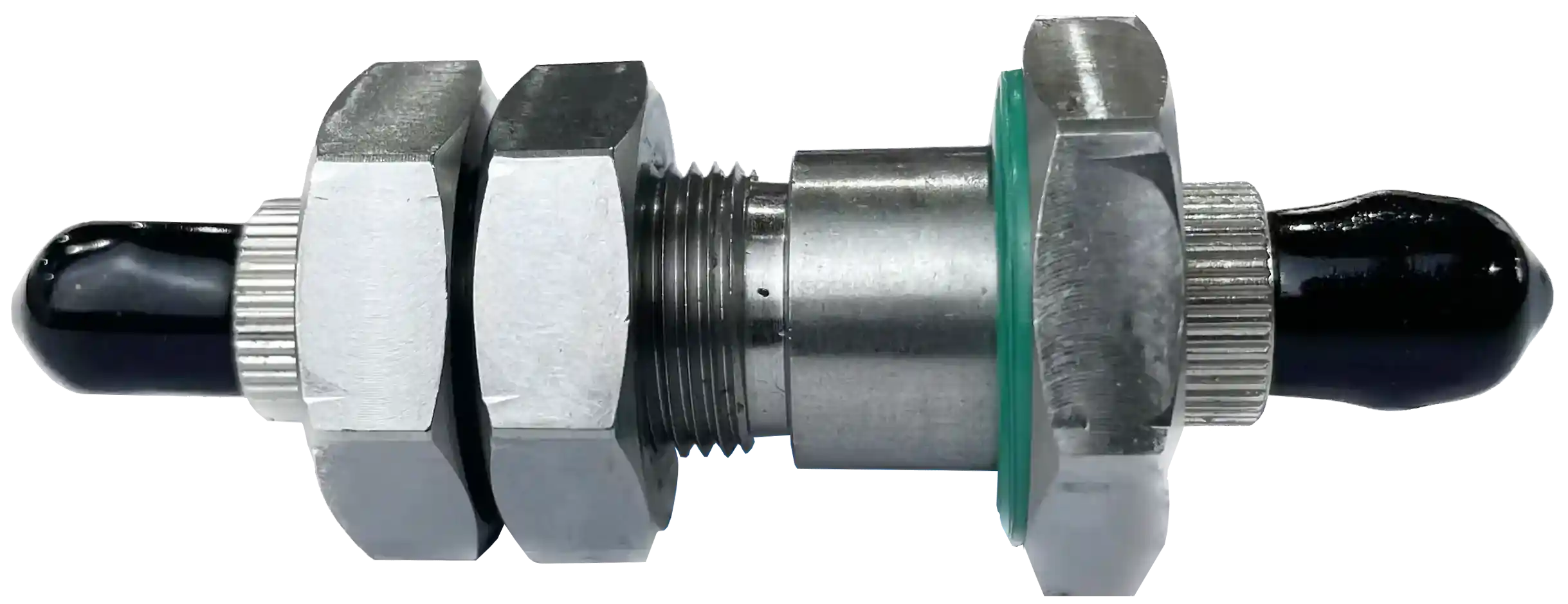
Transformer Fiber Optic Penetrator
A 316 stainless-steel optical penetrator that transitions between an internal transformer sensing probe and external optical fiber at the tank boundary.
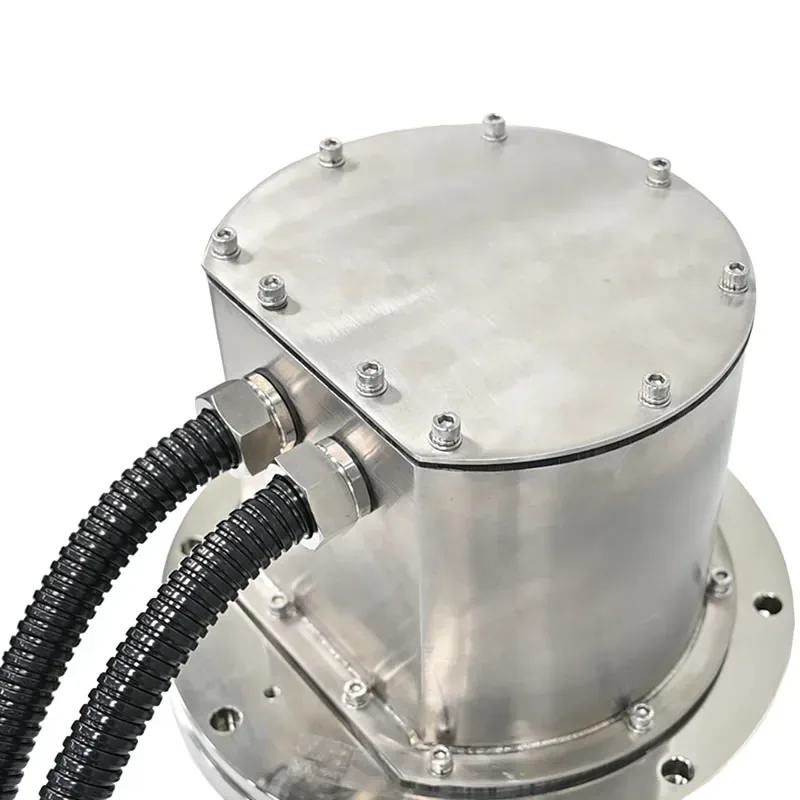
Transformer Fiber Optic Protective Cover
A 304 stainless-steel protective cover fitted over the transformer flange assembly to protect penetrators and external optical extension cables from mechanical damage and weather exposure.
PRODUCT CONFIGURATION REVIEW
Plan the Right Product Configuration
Tell us how this oil immersed transformer fiber optic temperature monitoring system will be used. INNO can review the measurement point, installation route, channel requirements and system interface against the selected product.
- Measurement target: Oil-immersed transformers
- Installation method: Coordinate probe positions, tank-boundary routing components, channel count and monitoring outputs with the transformer build and operating plan.
- Product selection: Transformer construction and approved hot-spot locations
- System requirement: Required channels, alarms, display and supervisory integration
Include the operating temperature range, number of measurement points and required communication or alarm outputs where applicable.