
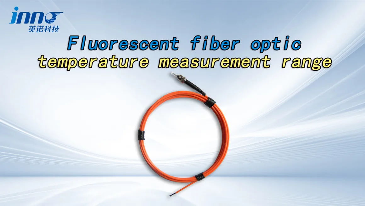
Choosing a fiber optic temperature sensor requires matching the probe, fiber length, channel quantity and monitoring instrument to the actual measurement point. Before comparing models or prices, confirm seven things: temperature range, measurement location, probe structure, fiber length, number of sensing points, electrical environment and monitoring output.
Most selection problems happen when one of these is skipped. A probe can cover the correct temperature range and still not fit the winding gap. A transmitter can be ordered before anyone has confirmed how many points need monitoring. This guide goes through each decision in the order engineers and buyers usually make them, so you can define a complete configuration before requesting a quotation.
Key Takeaways
- Confirm the temperature range first. Base it on the normal operating temperature, the expected maximum and a safety margin.
- Match the probe size and structure to the actual sensing point. Available space and contact method matter as much as the range.
- Base fiber length on the real routing distance, not the straight-line distance. About 3–5 m is a practical starting point for many equipment installations, but the installation route decides the final length.
- Count one probe for each defined sensing point. The total number of points you need to monitor tells you how many probes to order.
- Choose the monitoring instrument from the channel quantity and output interfaces. Select the instrument last, after the points and outputs are known.
Fiber Optic Temperature Sensor Selection at a Glance
| Selection Factor | What to Check | Selection Direction |
|---|---|---|
| Temperature Range | Normal operating temperature, expected maximum, required margin | Choose a probe whose rated range covers the maximum plus a margin; typical configurations cover about -40 to 260 °C |
| Probe Structure | Contact method, fixing method, insulation requirement | Use a bare or compact tip for embedded points and a fixable or sheathed structure for surface contact |
| Probe Diameter | Gap, slot or hole size at the sensing point | Typically about 2–3 mm; choose the smaller option for winding gaps and tight slots |
| Fiber Length | Routing path from the sensing point to the instrument, including bends and exits | Start from 3–5 m for equipment-mounted instruments and add length for external or remote routing |
| Number of Sensing Points | How many locations must be measured at the same time | One probe for each point; the total number of probes sets the channel count |
| Electrical Environment | High voltage, EMI, RF, microwave or strong magnetic field | Use an all-dielectric probe and fiber, and place the instrument outside the field |
| Mechanical Protection | Vibration, abrasion, oil, pulling during assembly | Add a protective sleeve or jacket on exposed fiber sections and fix the fiber along its route |
| Monitoring Instrument | Channel quantity, mounting location, need for a local display | Use a low-channel unit for 1–4 points and a multi-channel transmitter or monitor for larger point counts |
| Communication / Output | PLC, SCADA or DCS connection, alarm logic | Specify RS485/Modbus, an analog output or alarm relays at the quotation stage |
Step 1: Define the Temperature Range
Start with the temperatures the measurement point will actually see. Confirm these four items:
- Normal operating temperature: the steady-state value during regular operation.
- Expected maximum temperature: the highest value during overload, fault or test conditions.
- Required measurement margin: headroom above the expected maximum, so readings stay within the rated range.
- High or low temperature configuration: whether the application needs extended high-temperature or low-temperature capability.
As a general reference, typical fluorescent fiber optic configurations cover approximately -40 to 260 °C depending on probe design. Typical accuracy is ±0.5 to ±1 °C, with a response time of <1 s. The final range depends on the selected probe configuration, because the probe materials and structure set the usable limits.
- Transformer winding: Cover hot-spot temperatures during overload, not only the normal load.
- Electrical connection / busbar: Include the temperature rise that a deteriorating joint could cause.
- Microwave / test equipment: Confirm the peak temperature of the test cycle, which can exceed the normal process temperature.
Step 2: Identify the Measurement Point
Do not start by picking a product model. First define exactly where the temperature will be measured. Common measurement points include:
- Transformer winding hot spots
- Busbar joints
- Cable connections
- Motor and generator windings
- Test objects
- Microwave heating areas
- High-voltage components
For each point, answer these questions:
- How much space is available around the point?
- Can the probe contact the target directly?
- Is there a fixed position to hold the probe in place?
- Is there a strong electric or magnetic field nearby?
- How will the fiber be routed out of the equipment?
Step 3: Choose the Probe Structure and Diameter
The measurement point sets the requirements for the probe. Typical probe diameter is around 2–3 mm depending on structure, with smaller options suited to tight winding gaps.
| Application | Probe Selection Focus |
|---|---|
| Transformer winding | Small diameter, insulation compatible with transformer oil or paper, and suitability for winding placement |
| Dry-type transformer | Compact probe that can be placed at multiple winding points for each phase |
| Busbar / electrical connection | Mechanical fixing and reliable direct contact with the joint surface |
| Motor / generator | Compact structure that can follow the winding and slot routing |
| Microwave / RF | Fully non-metallic optical sensing path |
| High-voltage testing | Electrical isolation and enough routing distance to reach a safe instrument location |
| MRI / strong magnetic field | Non-conductive, non-metallic configuration throughout the probe and fiber |
Step 4: Select the Fiber Length
Fiber length is mainly determined by the real routing distance between the sensing point and the monitoring instrument. For many conventional equipment projects, 3–5 m is a reasonable starting reference. Adjust it based on these factors:
- Equipment size
- Internal routing path
- Bend path and minimum bend radius
- Instrument mounting position
- Installation allowance for fixing and service
- External routing distance outside the equipment
Typical examples:
- Small cabinet: About 3 m may be sufficient when the instrument is mounted nearby.
- Transformer / larger equipment: 3–5 m or longer may be required to route the fiber from the winding to the tank wall or control box.
- Laboratory / test bench: Length depends on the distance between the test zone and the data acquisition equipment.
Do not calculate fiber length from the straight-line distance alone. The fiber follows the equipment structure, so its real path is almost always longer.
Step 5: Determine the Number of Sensing Points
A fiber optic probe normally corresponds to one defined measurement point. The key question is: how many locations need to be measured simultaneously?
| Application | Channel Selection Logic |
|---|---|
| Transformer winding | Depends on the number of phases, the winding locations and the monitoring objectives, such as hot-spot only or hot-spot plus oil |
| Dry-type transformer | Usually based on at least one point per phase winding, plus any additional core or ambient points |
| Switchgear | Based on the number of contacts, cable terminations and compartments to be monitored |
| Busbar connections | One point for each critical joint; prioritize bolted connections with high current |
| Motor / generator | Based on the phases and the winding or bearing locations that need monitoring |
| Test bench | Based on the test plan and the number of points recorded per test object |
| Microwave equipment | Based on the number of sample positions or heating zones to be compared |
Step 6: Choose the Monitoring Instrument
Once you know the number of sensing points, select the transmitter or monitoring instrument. INNO configurations can support single-channel or multi-channel measurement, with the channel quantity selected according to the number of sensing points.
| Requirement | Suggested Direction |
|---|---|
| 1–4 points | Low-channel transmitter or compact monitoring unit |
| Multiple points | Multi-channel transmitter or monitoring instrument sized to the total probe count, with spare channels if expansion is planned |
| Local display | Instrument with a front-panel display for on-site reading |
| RS485 / Modbus | Instrument with a digital communication port for system integration |
| Analog output | Instrument with analog output channels, such as 4–20 mA, for existing control systems |
| Alarm relay | Instrument with relay outputs for local alarm or trip signals |
| OEM embedded equipment | Compact OEM fiber optic temperature module integrated into the host equipment |
| PLC / SCADA connection | Modbus communication or analog output, depending on what the control system accepts |
Step 7: Consider the Electrical Environment
Fiber optic temperature sensors are often selected because conventional electrical sensors struggle in certain environments. Thermocouples and RTDs rely on metallic leads, which can pick up interference, create a conduction path at high voltage or heat up in RF fields.
In high-voltage equipment, an all-dielectric probe and fiber provide inherent electrical isolation between the measurement point and the instrument. This allows direct measurement on energized parts such as windings and busbars.
In environments with strong EMI, RF or microwave energy, an optical signal is not affected by electromagnetic noise, and a non-metallic probe does not absorb field energy or distort the heating pattern.
In strong magnetic fields, such as MRI or large electrical machines, a non-conductive, non-metallic configuration avoids induced currents and magnetic interaction. In all of these cases, place the monitoring instrument outside the field and plan the fiber length to reach it.
Typical Selection Examples
Transformer Winding
Winding hot-spot monitoring requires probes that can be placed inside the winding structure and routed out of the tank.
- Temperature range covering overload hot-spot conditions
- Small probe diameter suited to winding placement
- Defined winding measurement point for each phase
- Fiber length from the winding to the tank wall and instrument
- Total sensing points based on phases and monitoring objectives
- Multi-channel instrument with communication output
Switchgear / Busbar
Connection monitoring focuses on detecting temperature rise at joints before a failure occurs.
- Location of each joint or connection
- Number of monitored connections
- Probe fixing method on the conductor
- Fiber routing through compartments
- Channel count across panels
- Monitoring output to the substation system
Microwave / RF Equipment
Measurement inside the field must not interfere with heating or be affected by the field.
- Fully non-metallic sensing path
- Temperature range for peak process conditions
- Probe structure suited to the sample or cavity
- Fiber routing through the cavity wall
- Instrument located outside the field
High-Voltage Test Equipment
Test setups need isolated measurement with the operator and instrument kept at a safe distance.
- Electrical isolation along the full fiber path
- Probe dimensions suited to the test object
- Fiber length to reach the safe measurement zone
- Number of test points per object
- Distance from the test object to the instrument
Quick Selection Table
| Requirement | Recommended Direction |
|---|---|
| Single temperature point | One probe with a suitable low-channel instrument |
| Several points in one piece of equipment | Multiple probes with a multi-channel monitoring instrument |
| Transformer winding | Small-diameter insulated probes with a multi-channel transmitter |
| Electrical cabinet / busbar | Fixable contact probes with a multi-channel monitor and communication output |
| Microwave / RF | Non-metallic probe, with the instrument outside the field |
| Strong magnetic field | Fully non-conductive probe with an extended fiber length |
| Laboratory test bench | Probes matched to the test points, with an instrument that has a data output |
| OEM equipment | Probe with an OEM fiber optic temperature module |
These are initial selection directions only. Confirm the final probe structure, fiber length and channel configuration against the actual equipment.
Fiber Optic Temperature Sensor Buying Checklist
Before requesting a quotation, prepare the following:
- □ Equipment type
- □ Measurement location
- □ Temperature range
- □ Number of sensing points
- □ Required fiber length
- □ Available probe space / required diameter
- □ Electrical environment
- □ Mechanical protection requirement
- □ Monitoring instrument requirement
- □ RS485 / Modbus requirement
- □ Analog output requirement
- □ Alarm relay requirement
- □ OEM requirement
Common Selection Mistakes
- Choosing fiber length from the straight-line distance. Bends, internal routing and instrument position add length, so a fiber sized this way often ends up too short.
- Selecting the monitoring instrument before confirming the channel quantity. This can leave points unmonitored or force you to add a second unit later.
- Using the same probe structure for every measurement location. A winding point and a busbar joint need different sizes and fixing methods.
- Focusing only on temperature range while ignoring installation space. A probe with the correct range is still unusable if it does not fit the sensing point.