
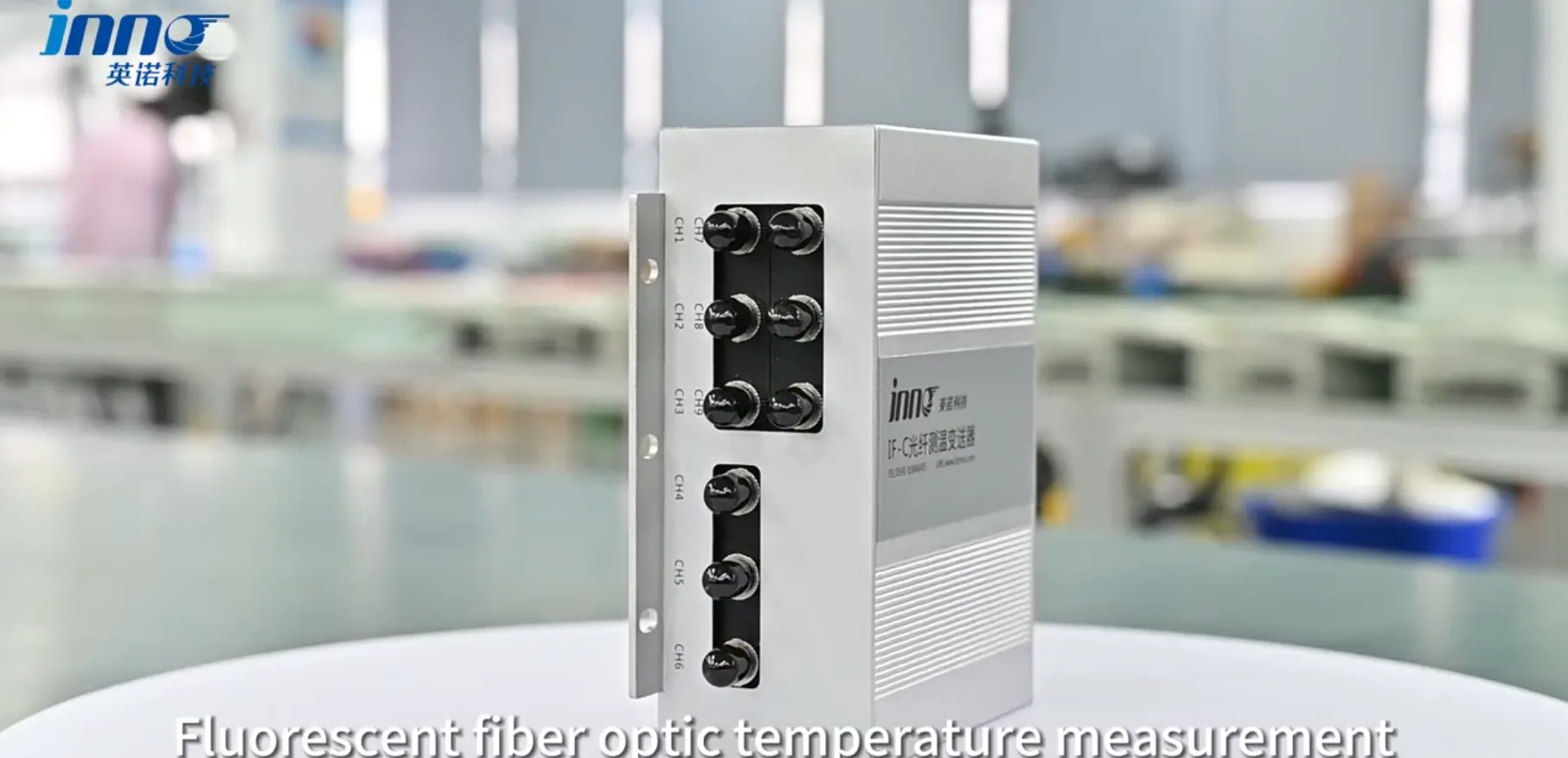
A fiber optic temperature converter is the instrument that turns the optical signal returned from a fiber optic temperature sensor into a temperature value that can be displayed, recorded or transmitted to another monitoring system. The sensor responds to temperature at a physical point. The converter sits on the instrument side of the chain, sending light into the fiber, reading what comes back and calculating the result. In a fluorescence-based system, that calculation relies on how the fluorescence signal from the sensing tip behaves as temperature changes.
INNO focuses on fluorescence-based point fiber optic temperature sensing, and this article follows that scope. It explains what happens after the optical signal returns to the instrument, how the converter relates to the probe, and how the terms converter, transmitter, demodulator and interrogator overlap.
Key Takeaways
- The sensor and the converter are different parts of the measurement chain. The sensor responds to temperature, and the converter reads and processes the optical signal.
- The sensing tip is the part that responds to temperature. The rest of the optical fiber does not act as the temperature sensor in a fluorescence point-sensing system.
- The optical fiber carries excitation light to the sensing tip and carries the returned optical signal back to the instrument.
- The converter processes the returned signal and calculates a temperature value.
- Fluorescence systems use fluorescence decay behavior at the sensing tip. They do not measure temperature along the entire fiber.
- Converter, transmitter, demodulator and interrogator are related terms, but manufacturers do not always use them identically.
- Channel count must match the number of independent sensing points.
What Is a Fiber Optic Temperature Converter?
"Fiber optic temperature converter" is a broad search and engineering term. It is not a strictly standardized device name recognized the same way worldwide. It generally refers to the instrument that receives an optical sensing signal, processes or demodulates it, and converts the result into a temperature value or a usable output.
Different manufacturers describe similar equipment as a converter, transmitter, demodulator, interrogator, measurement instrument, monitor or host. These names overlap, but they are not always interchangeable. This article uses "converter" as the general term and points out where other names emphasize different aspects.
Depending on instrument design, a converter may be responsible for:
- optical excitation of the sensing element
- receiving the returned optical signal
- signal conditioning
- demodulation of the temperature information
- temperature calculation
- digital processing
- display or data output
Not every instrument covers every function. Some units include a local display, while others send data to a separate host. Interfaces such as Ethernet, RS485, analog current output or relay contacts are common in industrial instrumentation generally, but whether a given converter provides them depends on the specific instrument and interface configuration.
Fiber Optic Temperature Sensor and Converter Are Different Components
A common source of confusion is treating the sensor and the converter as one device. They perform different jobs.
The sensor, or probe, senses temperature at a physical point. In a fluorescence system, this happens at a fluorescent sensing tip at the end of the fiber. Fiber optic temperature sensors are typically passive at the point of measurement: the probe contains no electronics that calculate temperature.
The converter, or demodulator, receives and processes the optical signal. It provides the excitation light, reads the returned signal and derives temperature from it.
A typical signal chain looks like this:
temperature
   ↓
fluorescent sensing tip
   ↓
optical fiber
   ↓
returned fluorescence signal
   ↓
converter / demodulator
   ↓
temperature value
   ↓
display / monitoring / control system
This chain is the core of the topic. The tip converts a physical temperature into a change in optical behavior. The fiber carries the optical signals in both directions. The converter turns the returned optical signal back into a number an engineer or control system can use.
For a detailed explanation of the sensing element itself, the site already has an article on what a fiber optic temperature sensor is and how it works. This article concentrates on the instrument side.
How Fluorescence Fiber Optic Temperature Conversion Works
Fluorescent fiber optic temperature sensing uses a fluorescent material at the probe tip whose emission behavior depends on temperature. The converter interprets that behavior. The steps below describe the general sequence without assuming any specific wavelength, timing value or algorithm, since these vary by design.
1. Optical Excitation
The instrument sends excitation light through the optical fiber toward the probe. The light source and its control are part of the converter.
2. Fluorescent Sensing Tip
At the end of the fiber, the sensing material at the probe tip absorbs the excitation light and is excited.
3. Fluorescence Decay
The material then emits fluorescence. After excitation ends, the emission fades over time, and the way it decays varies with the temperature of the material. This decay behavior is what carries the temperature information.
4. Return Optical Signal
The fluorescence signal travels back through the optical path to the instrument. The same fiber commonly serves both directions, though the exact optical arrangement depends on the design.
5. Signal Demodulation
The converter processes the returned signal. Demodulation here means extracting the temperature-dependent information, in this case the decay behavior, from the raw optical signal.
6. Temperature Calculation
The instrument converts the measured fluorescence decay behavior into a temperature value using its calibrated relationship between decay behavior and temperature. This calibration is part of why sensor and instrument need to be compatible.
7. Output
The temperature result can then be displayed, logged or sent to another system, depending on the interfaces the instrument provides.
Because the measurement relies on decay behavior rather than on how bright the returned light is, it is less dependent on simple intensity changes in the optical path. That is one reason fluorescence lifetime methods are used for point temperature measurement.
Converter, Transmitter, Demodulator and Interrogator
These four terms appear together often, and the differences are mostly about emphasis. Manufacturers may use them differently, so the table describes typical usage rather than fixed definitions.
| Term | What the Name Emphasizes | Typical Role | Important Note |
|---|---|---|---|
| Converter | Conversion of a sensing signal into temperature data or a usable output | Receives the optical signal and produces a temperature value or output | A broad term, not a strictly standardized device category |
| Transmitter | Delivering the measured temperature to another control or monitoring system | Provides temperature data through an output or communication interface | Some products called transmitters also perform the optical reading, while others may only relay data |
| Demodulator | Extracting temperature information from the returned optical signal | Processes the optical signal to recover the temperature-dependent quantity | Focuses on the signal-processing step, which may be one part of a larger instrument |
| Interrogator | A broad fiber optic sensing term for an instrument that excites and reads optical sensors | Sends light to the sensor and reads the response | Used across many sensing technologies, so the term alone does not identify a specific principle or architecture |
| Measurement instrument | The complete reading instrument as a general category | Performs sensing readout, processing and output as one unit | A general term that does not specify architecture or function set |
Two cautions apply. Converter and transmitter are not exactly the same thing, even though a single product may act as both. And interrogator does not always mean one specific architecture: an interrogator for one optical sensing method is different from one designed for another.
For products where the emphasis is on delivering temperature data to other systems, see fiber optic temperature transmitters and hosts.
Instruments also come in different physical forms. Some are standalone units, and others are embedded modules intended for integration into a larger piece of equipment. Fiber optic temperature modules and instruments covers the range of forms available for OEM and standalone use.
What Does a Channel Mean in a Fiber Optic Temperature Converter?
For point sensing, one independent sensing point normally requires one compatible active measurement channel. A channel is the path through which the instrument excites one probe and reads its return signal.
The relationship can be summarized as:
1 probe ≈ 1 sensing point ≈ 1 compatible active channel
As a conceptual example, measuring four independent physical locations would normally require four probes and at least four compatible active channels. This is only an illustration. Converters are not all built with the same channel count, and the number of channels available depends on the specific instrument.
Point Measurement Is Not Distributed Temperature Sensing
A fluorescence probe measures temperature at the sensing tip. The optical fiber between the probe and the instrument does not automatically provide a continuous temperature profile along its length.
Having multiple channels does not turn a system into distributed temperature sensing (DTS). Multiple probes provide multiple independent point measurements, each tied to a known location chosen by the engineer. Distributed technologies use different sensing principles and different interrogation methods, and they are outside the scope of INNO's fluorescence point-sensing approach.
How Temperature Data Leaves the Converter
Once the converter has calculated a temperature value, that value can be used in several ways:
- displayed locally on the instrument
- logged for later analysis
- transmitted digitally
- sent to a PLC
- sent to a SCADA system
- integrated into a broader monitoring system
Which of these are available depends on the specific instrument and interface configuration. A compact OEM module may output digital data for a host device to handle. A standalone instrument may include its own display and communication ports. The available options should be confirmed for each instrument rather than assumed.
When the data feeds into a larger system that combines multiple sensors, data handling, alarms and software, it becomes part of a fiber optic temperature monitoring system. The converter provides the temperature data, and the monitoring system decides what to do with it.
Components of a Fiber Optic Temperature Measurement System
A complete fiber optic temperature measurement system can be described in terms of the components below. Not every project needs every component, and the way they are packaged varies.
| Component | Function | Example Role |
|---|---|---|
| Fluorescent sensing tip / probe | Responds to temperature at a physical point | Placed at the location where temperature is to be measured |
| Optical fiber | Carries excitation light and the returned optical signal | Connects the probe to the instrument over the required distance |
| Connector / interface | Joins the fiber path to the instrument | Provides a compatible optical connection between probe and converter |
| Temperature converter / demodulator | Reads the returned signal and calculates temperature | Produces a temperature value from the optical signal |
| Monitoring software or host system | Collects, displays, records or analyzes temperature data | Provides trends, logs and alarm handling, depending on design |
| PLC / SCADA integration | Passes temperature data to control or supervisory systems | Allows temperature to be used in process control or plant monitoring |
For a broader introduction to the measurement technology as a whole, see fiber optic temperature measurement.
Fiber Optic Temperature Converter vs Monitoring System
The two terms are related but describe different scopes.
The converter reads, demodulates and converts the sensor signal. Its job is to produce temperature data from optical signals.
A monitoring system is usually a larger, system-level concept. Depending on design, it may include multiple sensors, a converter or transmitter, data acquisition, a display, alarms, communication functions, software and system integration. The specific functions vary from one system to another.
A converter can be one component inside a monitoring system, but the converter should not be treated as the complete monitoring system. Conversely, some monitoring systems use more than one converter across different measurement locations.
Can Any Fiber Optic Sensor Work with Any Converter?
No, not automatically. Compatibility depends on several factors:
- sensing principle
- optical characteristics
- probe construction
- connector interface
- instrument calibration
- signal-processing method
- channel configuration
Fluorescence probes are not universally interchangeable across brands or designs, and a given instrument cannot be assumed to read any manufacturer's sensor. The calibration relationship between the probe's optical behavior and temperature is part of the match between probe and instrument.
Different Sensing Technologies Need Different Interrogation
A converter designed for fluorescence lifetime sensing cannot automatically read sensors based on FBG wavelength shift, GaAs absorption edge, Raman distributed sensing or other optical principles. These technologies use different optical excitation, different signal processing and different interrogation methods.
GaAs fiber optic temperature sensors, for example, use a different optical measurement principle from fluorescence lifetime sensors. For a comparison of those two approaches, see GaAs vs fluorescence fiber optic temperature sensors.
How to Choose a Fiber Optic Temperature Converter
The following checklist covers the main points to review. Not every project needs all of them.
- Sensor technology: confirm the instrument is built for the sensing principle being used, such as fluorescence lifetime.
- Number of sensing points: count the independent locations to be measured.
- Required channel count: match the number of compatible active channels to the sensing points.
- Supported probe type: confirm the instrument works with the intended probe construction.
- Measurement range required by the application: check that the system covers the expected temperature range.
- Required accuracy: define what the application actually needs.
- Response requirement: consider how quickly temperature changes must be tracked.
- Connector compatibility: confirm the optical interface between probe and instrument.
- Data interface: identify how the data must leave the instrument.
- Local display requirement: decide whether on-instrument readout is needed.
- PLC / SCADA integration: confirm the communication path to control or supervisory systems if required.
- Data logging requirement: decide whether the instrument or a separate system records data.
- Installation environment: consider the conditions around both the probe and the instrument.
- OEM or standalone instrument requirement: determine whether the unit is embedded in other equipment or used independently.
Where Are Fiber Optic Temperature Converters Used?
Converters are used wherever a fiber optic temperature measurement chain is applied. Typical areas include:
- Power transformers: measuring winding or internal temperatures where the sensing point sits in an electrically demanding environment.
- Motors and generators: measuring temperature at selected internal locations.
- High-voltage equipment: reading temperature at points that require electrical isolation.
- RF and microwave heating equipment: measuring temperature in fields that can disturb electrical sensors.
- Medical or strong magnetic-field environments: reading temperature where metallic sensors may be unsuitable.
- Industrial test systems: collecting point temperatures during equipment testing.
- Laboratory equipment: measuring temperature in research setups.
Why Use an Optical Temperature Measurement Chain?
From an engineering standpoint, an optical chain offers several practical characteristics:
- The sensing point can remain electrically isolated from the instrument.
- The optical signal path has high resistance to electromagnetic interference.
- It suits electrically demanding environments.
- Small probe geometry can support selected embedded measurements.
These are general characteristics, not guarantees. Actual performance depends on the implementation, including probe design, installation and instrument.
Common Misunderstandings About Fiber Optic Temperature Converters
The converter itself senses temperature
Usually it does not. The sensor or probe senses temperature, and the converter processes the optical signal that the probe returns.
The entire fiber measures temperature
Not in fluorescence point sensing. Temperature is measured at the sensing tip, and the fiber carries the optical signals between the tip and the instrument.
More channels turn the system into DTS
They do not. Multiple channels remain independent point measurements.
Any optical sensor can connect to any converter
Compatibility depends on the sensing principle and instrument design.
Converter and monitoring system always mean the same thing
They do not. System scope may be much larger than the converter alone.
Conclusion
A fiber optic temperature converter is the instrument-side part of the measurement chain that processes the optical signal from a compatible temperature sensor and converts it into usable temperature data.
Each part of the chain has a distinct role:
- Probe: senses the selected point.
- Fiber: carries optical signals.
- Converter / demodulator: processes the returned signal.
- Monitoring system: displays, records or integrates temperature data.
Terminology varies by manufacturer, so the name on a datasheet matters less than what the instrument does. What matters is sensing technology compatibility, channel count, the measurement requirement and the system interface.
If a project requires a fluorescence fiber optic temperature measurement instrument, INNO can help review sensor type, channel count, probe compatibility and system integration requirements.