Direct Measurement vs Estimated Temperature
Direct MeasurementActual hot spot measured
by fiber optic sensor
VSby fiber optic sensor
Estimated TemperatureCalculated from operating
data and thermal models
data and thermal models
 info@innofj.comContact Engineering
DIRECT FIBER OPTIC MEASUREMENT
 Direct PointMeasurement
 ElectricalIsolation
 EMIImmunity
 FastResponse
Traditional systems estimate hot-spot temperature using load, oil temperature and thermal models. Direct hot-spot temperature measurement measures the actual temperature at reviewed critical points inside the asset.
For transformer hot spot monitoring, the probe is placed at the selected winding or internal location rather than relying only on a model. Fluorescence fiber optic sensing provides a passive, non-conductive measurement path where electrical isolation and reliable measurement context are needed.
In a transformer, this is direct winding hot-spot measurement at the physical point of interest.
Surface readings and model-based estimates can miss the point that matters most. Direct point measurement provides a clearer temperature at the critical location for an informed engineering review.
INNO’s fiber optic sensors are built to perform in demanding environments across the power and industrial sectors.
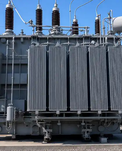
Monitor winding hot spots to optimize loading and extend transformer life.

Detect high-resistance connections before they lead to failure.

Protect assets by tracking winding temperatures in real time.

Ensure safe testing by measuring hot spots on test objects and terminations.

Monitor critical components that are sensitive to over-temperature.

Control and optimize process temperature in high-heat applications.
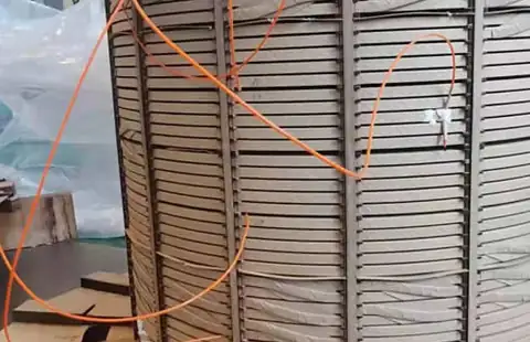
Install the fiber optic probe at the critical hot spot: winding, conductor, connection, or bushing.
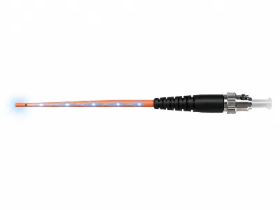
Pulsed or modulated light is delivered through the orange fiber to the sensing tip at the hot spot.
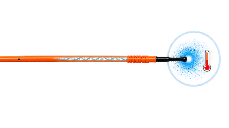
The optical return changes with temperature and returns through the same orange fiber.
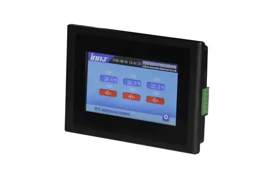
The INNO LCD display analyzes the return signal and outputs the actual hot-spot temperature in real time.
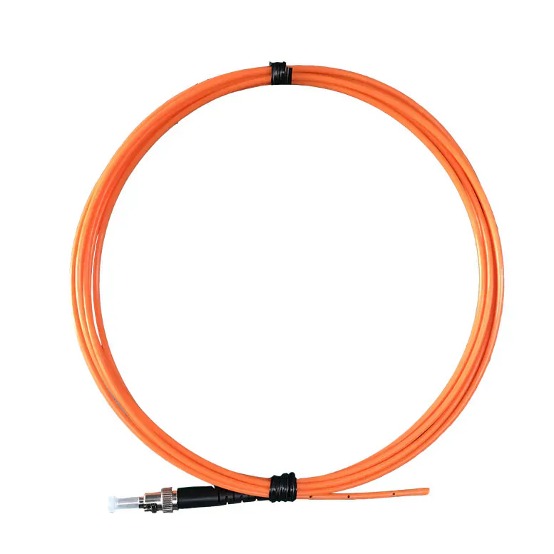
Installed at the hot spot to sense the actual temperature.
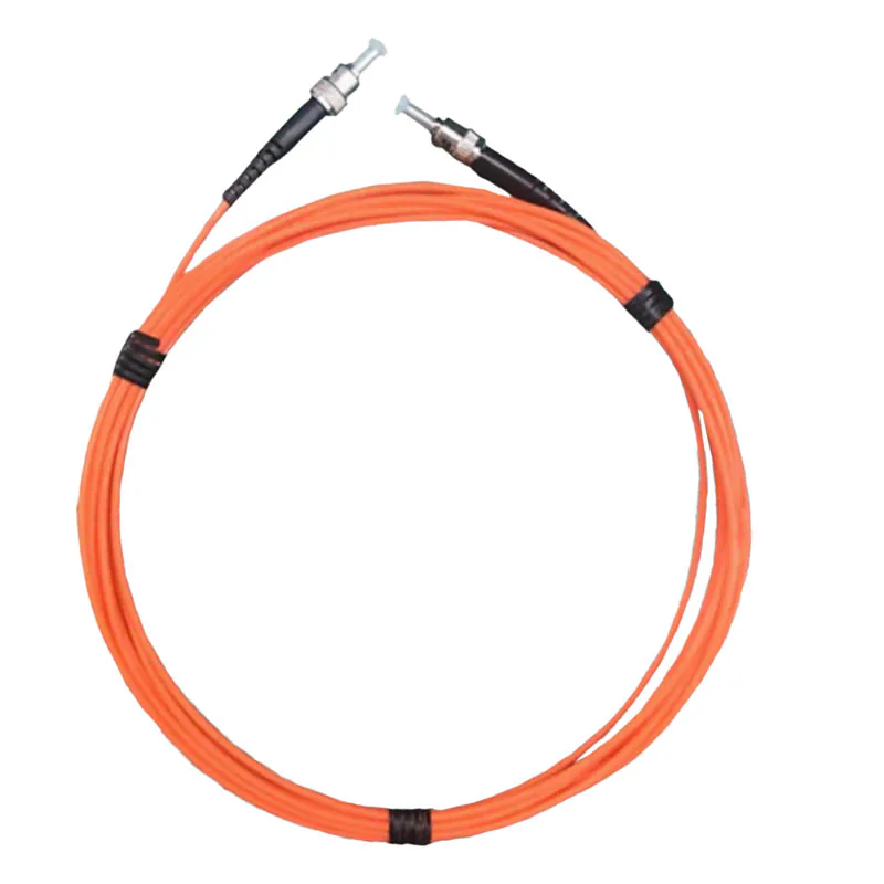
Extends the optical connection between the temperature probe and the measurement instrument.
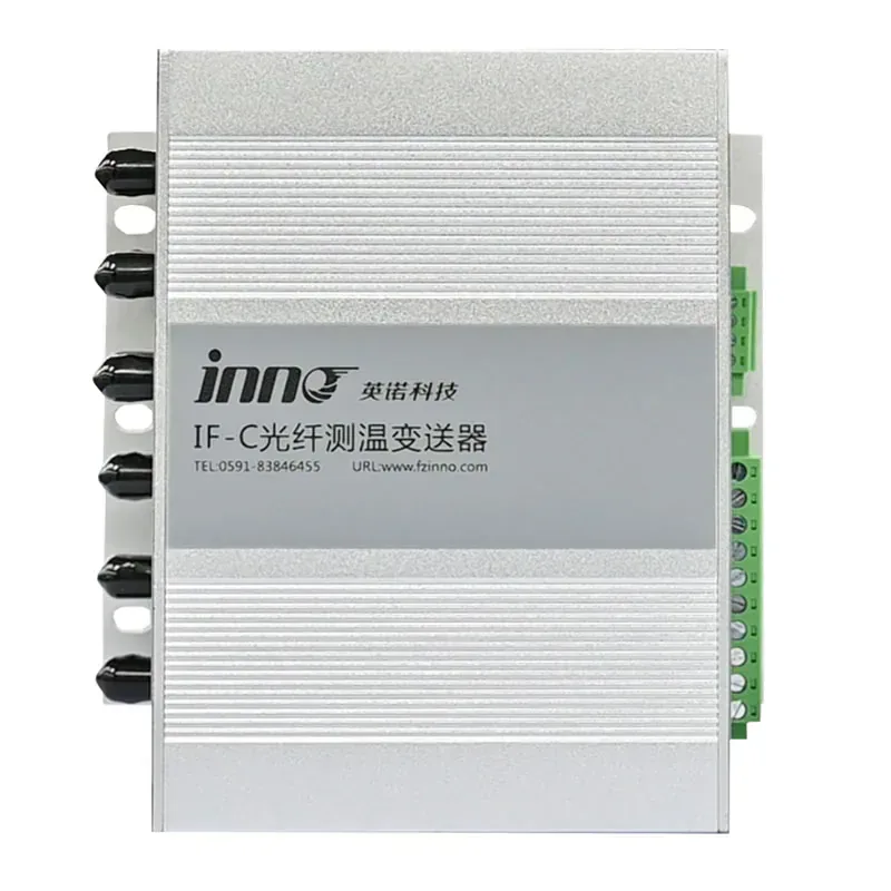
Decodes the optical signal and converts it to temperature data.
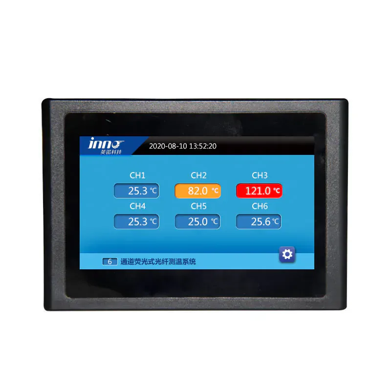
Displays real-time temperatures, trends, alarms, and system status.
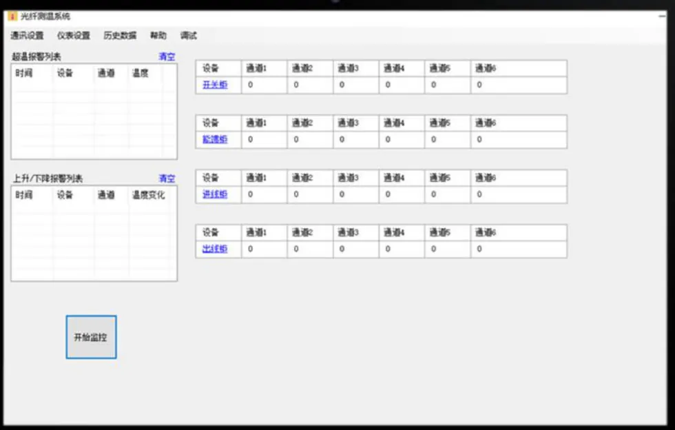
Receives data for alarms, control, logging, and remote monitoring.
Measures temperature at the selected point instead of relying on an estimate.
A dielectric sensing path separates the point from electrical circuits.
Optical transmission avoids electromagnetic pickup along the sensing path.
Probe dimensions and protection are selected for the available installation space.
One host can process multiple compatible probes; channel count follows the project plan.
Standard outputs and protocols support reviewed PLC, SCADA and data interfaces.
Choosing the right point ensures the measurement reflects the true thermal risk of the asset. Use the checklist below during design or review.
 Thermal Risk LocationSelect the point with the highest expected hot-spot temperature.
 AccessibilityEnsure the point can be accessed safely for installation and service.
 Mechanical ProtectionProtect the sensor from vibration, impact, and physical damage.
 Temperature RangeConfirm the sensor's rating covers the expected temperature range.
 Number of PointsDefine how many critical points must be measured.
 Installation StagePlan installation during manufacture or scheduled maintenance.
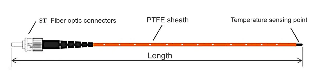 Single-Point Direct Measurement
Measures temperature directly at a defined sensing point.
Uses one fiber optic temperature probe.
Suitable for targeted temperature measurement.
Simple configuration for individual locations.
Multi-Point Temperature MonitoringMeasures multiple locations simultaneously.
Uses multiple probes with a multi-channel instrument.
Provides temperature distribution across selected points.
Supports continuous monitoring, alarms and data acquisition.
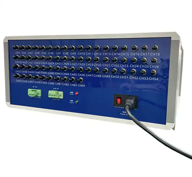
Multiple fiber optic probes can be combined with a multi-channel instrument for simultaneous point temperature monitoring.
Point probes selected around the hot-spot location and physical route.
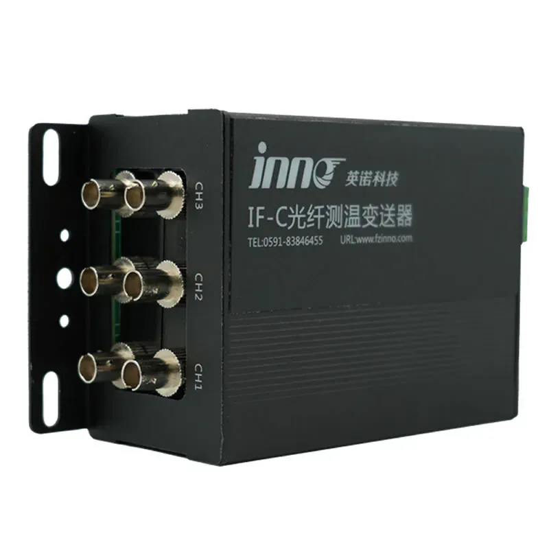
Signal acquisition for reviewed channel arrangements and local outputs.
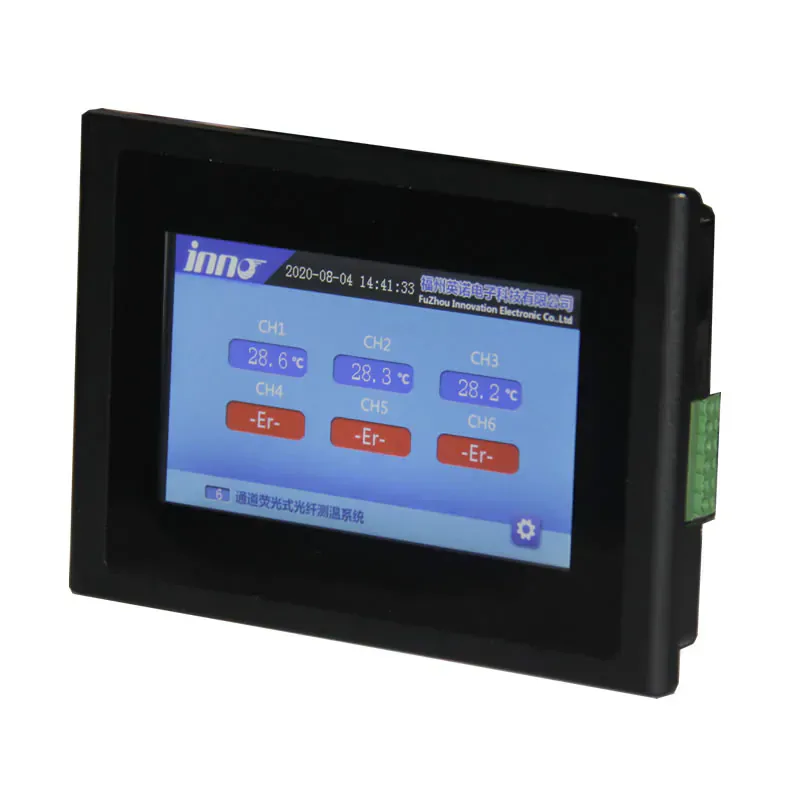
Local LCD display and alarm options for real-time temperature visibility.
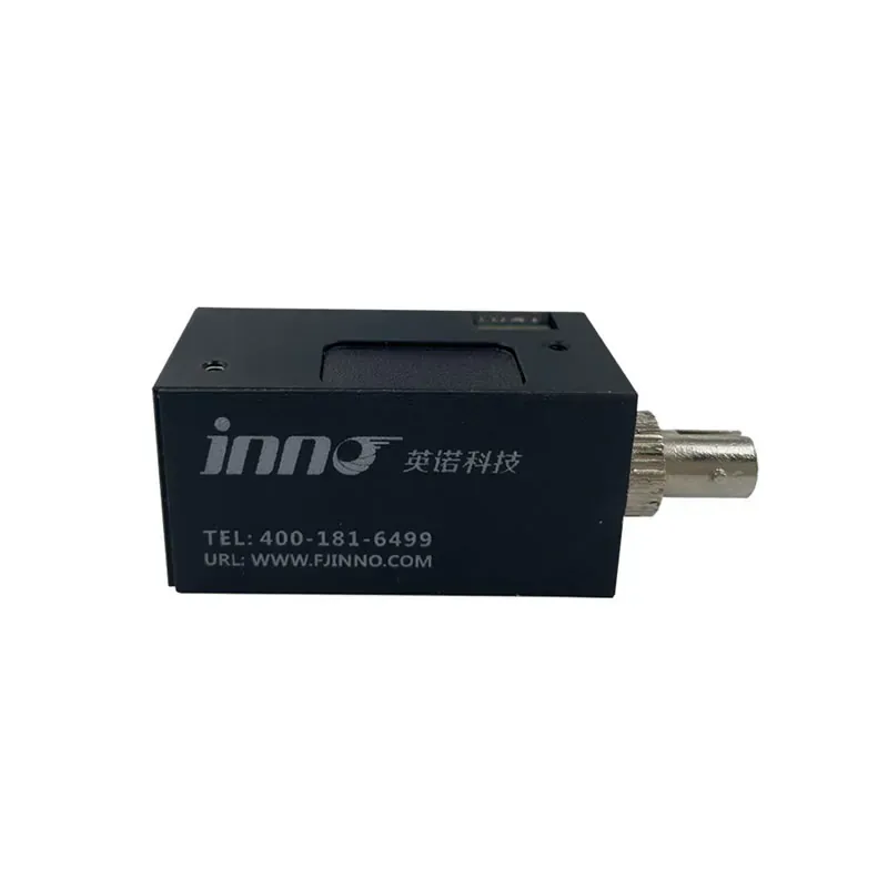
Compact modules for equipment builders with embedded sensing needs.
Measurement location
Maximum expected temperature
Number of measurement points
Fiber / probe length
Installation space
Mechanical protection requirement
Existing monitoring system
Required communication interface
You can also send your application details by email or WhatsApp for product selection and configuration support.
Email: info@innofj.com
WhatsApp / WeChat: +86 13599070393
A hot spot is a selected internal location where the highest thermal stress may occur, such as a winding, conductor or connection. Top-oil temperature represents the transformer oil condition and may not show the actual temperature at that critical point.
Depending on the selected probe and instrument configuration, the typical measurement accuracy is ±0.5°C to ±1.0°C. The final accuracy should be confirmed for the required temperature range and system configuration.
Yes. The sensing probe is passive and non-conductive, so the measurement point is electrically isolated and resistant to electromagnetic and radio-frequency interference.
INNO monitoring platforms can be configured from 1 to 64 independent channels. Each channel connects to one fiber optic point probe and measures one sensing-tip location.
The typical system response time is less than 1 second, allowing rapid visibility of temperature changes at the selected hot-spot location.
The sensing tip is positioned at the reviewed temperature point, while the optical fiber is routed to a compatible transmitter or monitoring host. Probe geometry, fiber length and mechanical protection are selected for the installation.
Yes. A compatible monitoring host can connect to PLC or SCADA systems through reviewed industrial communication interfaces such as RS485, and can also provide configured alarm or relay outputs.
Confirm the measurement location, expected temperature range, number of points, required probe and fiber length, installation space, mechanical protection, channel count, display requirements and communication interface.
Send the asset, target points and system requirements for an engineering review.