
Busbar & Bolt Connection Fiber Optic Temperature Probe
Direct optical point measurement at bolted busbar joints and electrical connection fasteners.
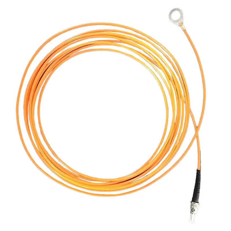
O-RING CONTACT TEMPERATURE PROBE
Place the Sensing Point Beneath the Fastener
The copper O-ring assembly fits beneath a selected bolt so the fluorescent sensing point follows the temperature of the bolted electrical connection.
The probe is passive and requires a compatible fluorescence instrument. It measures one defined connection point and is not a complete monitoring system or distributed temperature sensing cable.
- O-ring contact arrangement for selected bolted joints
- -40 °C to +260 °C range
- 1–15 m configurable fiber length
- Passive optical measurement path
Product Overview
The busbar and bolt connection fiber optic temperature probe is a passive optical probe built around a copper O-ring sensing assembly. It is intended to place the measurement point at a reviewed bolted electrical connection, where local heating can develop at the contact interface.
The probe must be used with a compatible fluorescence instrument. Final installation should consider the fastener arrangement, contact surfaces, optical-fiber exit path and the practical service access required around the connection.
JOINT MEASUREMENT
Why Bolted Joints Need a Fixed Sensing Position
A temperature reading only helps if it represents the connection being evaluated. The ring-style assembly supports a defined location at the application-specific fastener.
- Targets a specific bolted connection rather than ambient cabinet temperature.
- Supports point-by-point planning across multiple joints.
- Keeps the sensing path optical at the measurement location.
INSTALLATION REVIEW
Planning Ring-Style Mounting at a Busbar Connection
The mechanical joint must remain appropriate for the asset design. Review the mounting stack and fiber route before the selected configuration is released.
- Confirm bolt and connection arrangement.
- Protect the optical exit path from pinch points and sharp edges.
- Confirm compatible host channel and connector arrangement.
SHARED MEASUREMENT PRINCIPLE
Passive Point Sensing With a Compatible Instrument
The fluorescent sensing tip measures one selected point. A compatible instrument supplies the optical excitation, processes the returned signal and provides the temperature output. See the standard fluorescence probe for the full measurement principle.
PRODUCT CONSTRUCTION
Ring-Style Fiber Optic Probe Construction
The probe construction is organized around a stable sensing position at a selected bolted electrical connection.
Copper O-ring interface
The ring-style assembly is positioned beneath the selected fastener to keep the sensing location associated with that joint.
Defined joint position
One probe is planned for one chosen connection point rather than for the entire busbar assembly.
Optical fiber lead
The fiber leaves the connection and is routed to a compatible fluorescence instrument.
PRODUCT SELECTION
When to Choose the Busbar Bolt Probe
Choose this construction when the target temperature is a bolted electrical joint and the sensing assembly can be secured beneath the fastener.
- Busbar bolted joints
- Switchgear and electrical cabinet connections
- Defined contact-temperature points
- Projects requiring direct fastener-mounted measurement
- Applications with planned optical-fiber routing
APPLICATION-SPECIFIC ADVANTAGES
Key Probe Features
Fastener-Mounted Contact
The O-ring construction places the sensing assembly at the selected bolted connection.
Defined Point Measurement
Each probe measures one joint rather than averaging a larger enclosure.
Electrical Isolation
The temperature signal is carried optically to the connected instrument.
EMI Immunity
Optical transmission avoids electromagnetic pickup around energized equipment.
Configurable Fiber Route
fiber lengths can be application-specific around panel and cabinet layouts.
Application Review
Bolt size, contact pressure, clearances and routing are confirmed before ordering.
TECHNICAL SPECIFICATIONS
Technical Specifications
Choose the final probe construction and compatible instrument for the application.
Parameters to Confirm Before Ordering
INSTALLATION PLANNING
Plan the Bolt Interface and Fiber Route
The sensing tip must contact the actual temperature point while the optical route is protected through the equipment.
Target Point
Optical Route
Compatible Instrument
- Confirm the target bolt size and available mounting surface.
- Place the O-ring at the intended thermal contact location.
- Route and fix the optical fiber without exceeding the reviewed bend radius.
- Connect each probe to one compatible optical measurement channel.
PRODUCT TO INDUSTRY
Typical Applications
Open the related industry or solution page for application-specific measurement and installation guidance.
Switchgear Connections
Monitor selected bolted joints and connection points inside switchgear assemblies.
Transformer Connections
Review direct point measurement at selected transformer terminal and connection locations.
High-Voltage Testing
Instrument bolted test connections where an optical temperature path is preferred.
RELATED PRODUCTS
Compatible Products for This Application
These products have different roles in the measurement path and are selected according to the installation.
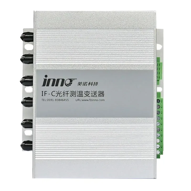
Multi-Channel Fiber Optic Temperature Transmitter
Centralizes several selected busbar or connection-point measurements.
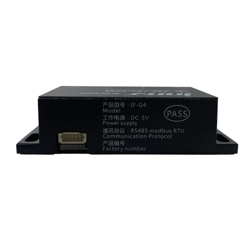
IF-G4 Four-Channel OEM Temperature Module
Adds compact optical acquisition to switchgear or equipment designs.
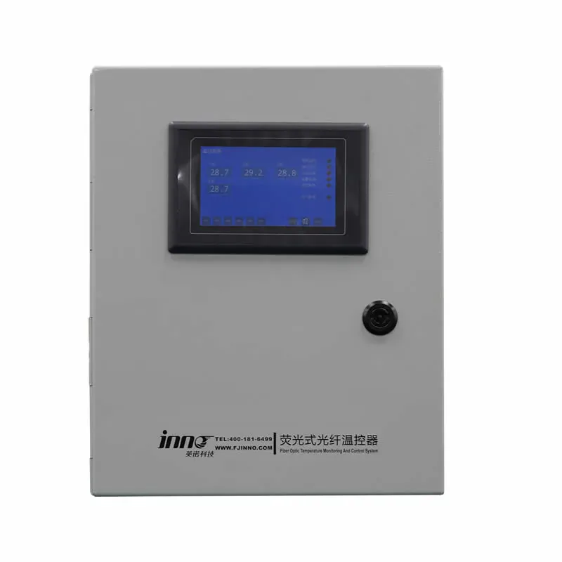
Dry-Type Transformer Monitoring System
A configured system for dry-type transformer winding measurement points.
BUYER QUESTIONS
Frequently Asked Questions
Does the busbar bolt probe measure the whole busbar?
No. It measures temperature at the selected O-ring contact point beneath one fastener.
Can it work without a monitoring instrument?
No. A compatible fluorescence instrument is required to excite the probe and calculate temperature.
What should be confirmed before ordering?
Confirm the bolt interface, target temperature range, fiber route and length, clearances, number of points and compatible instrument.
Is the fiber length configurable?
The standard configuration supports 1–15 m configurations. Final length and connector arrangement should be confirmed for the project.
Is this distributed temperature sensing?
No. It is a passive point probe that measures at the selected busbar or bolt connection.
Can it be used in high-voltage equipment?
Its optical measurement path is intended for electrically demanding environments, but the complete installation and insulation design must be reviewed.
PROBE SELECTION SUPPORT
Configure a Probe for Your Bolted Connection
Share the busbar or connection drawing, bolt dimensions, temperature range, fiber route, point quantity and required instrument.
- Measurement location
- Required temperature range
- Fiber route and length
Need Help Selecting the Correct Probe Construction?
Share the measurement point, environment and installation constraints with INNO.