
Temperature can be measured in strong electromagnetic fields using sensors and signal paths that are either well protected from interference or inherently non-electrical at the sensing point. Conventional electrical sensors such as RTDs and thermocouples can work in many industrial environments, but their conductive leads and low-level electrical signals may require careful shielding, grounding and routing when EMI is severe.
This guide focuses on fluorescence-based point fiber optic temperature sensors for strong electromagnetic environments. Fiber optic point sensors provide another approach by using an optical sensing path with no electrical measurement signal at the probe location.
For high-voltage, RF, microwave, transformer winding, generator and strong magnetic-field applications, optical sensing is often considered when electrical isolation and EMI immunity are important.
Key Takeaways
- Strong electromagnetic fields can affect temperature measurement mainly through the sensor wiring, signal path and instrumentation.
- PT100 and thermocouples can still be used when shielding, grounding and installation are properly designed.
- Fiber optic temperature probes avoid electrical signal transmission along the sensing fiber.
- High voltage, RF, microwave and strong magnetic fields are common environments where optical sensing may be preferred.
- One point probe measures one defined location; multiple points require multiple probes and monitoring channels.
- Sensor selection should consider temperature range, probe structure, routing distance, channel count and required outputs.
Temperature Measurement Options in Strong Electromagnetic Fields
| Method | Signal Type | EMI Sensitivity | Electrical Isolation | Typical Use |
|---|---|---|---|---|
| Fiber Optic Temperature Sensor | Optical | Very low along the optical path | High | Direct point measurement in electrically sensitive environments |
| PT100 / RTD | Electrical resistance | Depends on wiring and instrumentation | Depends on installation | Industrial equipment, machinery, dry-type transformer monitoring |
| Thermocouple | Low-level electrical voltage | Depends on shielding and wiring | Depends on installation | Industrial process and high-temperature measurement |
| Infrared | Optical / non-contact | Not affected by conducted electrical noise at sensing point | Yes | Accessible surface measurement |
| Thermal Model | Calculated | Not a physical point sensor | N/A | Estimated equipment temperature |
Why Strong Electromagnetic Fields Can Affect Temperature Measurement
EMI does not simply change the physical temperature — it mainly affects the electrical sensor signal, wiring, data acquisition, grounding and signal conditioning.
Common interference sources include high current, switching devices, transformers, generators, motors, busbars, RF transmitters, microwave systems and high-voltage test equipment.
Effects can include unstable readings, induced noise, measurement drift and communication disturbance. Not all electrical sensors fail in these environments — the outcome depends on how the measurement loop is designed.
Method 1: Fiber Optic Temperature Measurement
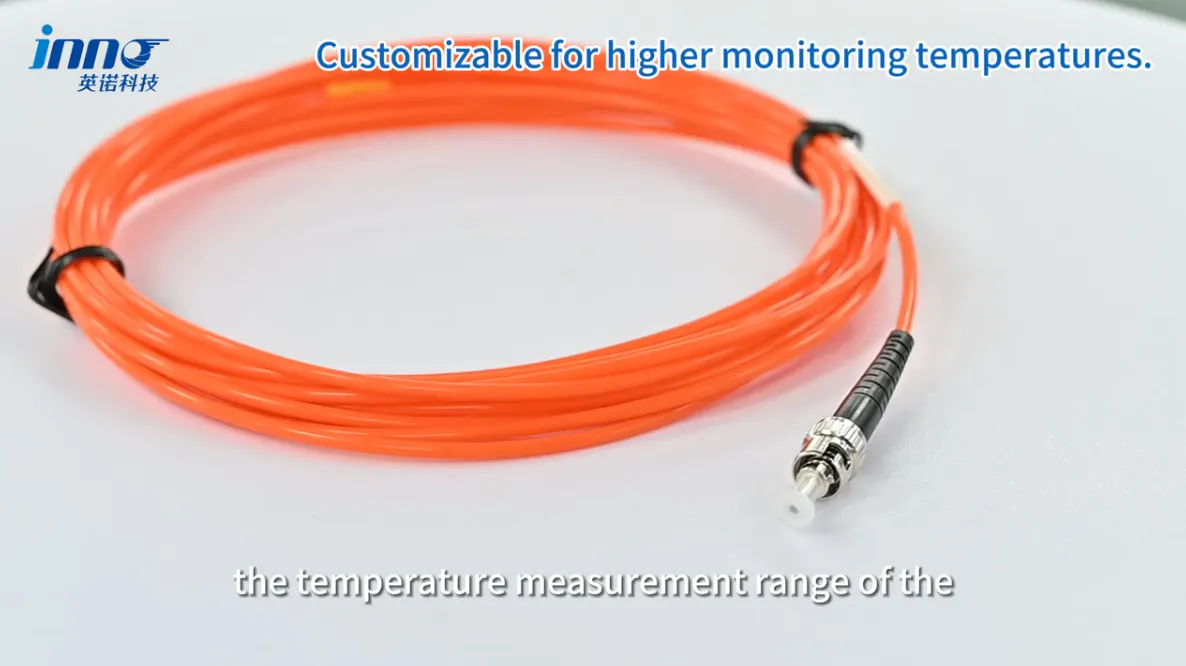
Fiber optic temperature sensing uses an optical path between the sensing point and the monitoring instrument. Key characteristics include no electrical signal at the sensing point, a non-conductive optical fiber, electrical isolation, and EMI/RFI immunity along the sensing path — making it suitable for point measurement in electrically sensitive locations.
| Parameter | Typical Value |
|---|---|
| Temperature Range | -40 to 260 °C |
| Accuracy | ±0.5 to ±1 °C |
| Response Time | <1 s |
| Probe Diameter | Approximately 2–3 mm |
| Fiber Length | Configured according to installation distance |
Exact specifications depend on probe configuration.
Method 2: PT100 / RTD Measurement
PT100 sensors are widely used in electrical and industrial equipment, offering a familiar industrial interface, wide support from PLCs and temperature controllers, suitability for many conventional installations, and a range of available probe constructions.
In EMI environments, considerations include lead wire routing, shielding, grounding, 3-wire or 4-wire arrangements, instrument input design, and isolation where required.
PT100 can work in electrically noisy environments, but the complete electrical measurement loop must be designed correctly.
Method 3: Thermocouple Measurement
Thermocouples are common where broad temperature range, high-temperature capability and industrial process measurement are important.
In strong EMI environments, factors to consider include the low-level thermoelectric signal, extension cable selection, shielding, grounding, cable routing and signal conditioning.
Thermocouples can be effective when the electrical installation and acquisition system are designed for the environment.
Method 4: Infrared and Non-Contact Temperature Measurement
Infrared measurement avoids direct electrical contact with the target, making it suitable for accessible surfaces such as busbar surfaces, terminals, machine surfaces and open equipment.
Limitations include the need for line of sight, measurement limited to surface temperature, inability to directly see internal winding temperatures, and sensitivity to emissivity and surface condition.
When Fiber Optic Temperature Sensing Is Especially Useful
Transformer Windings
Direct point measurement inside electrically stressed winding structures.
Generator and Motor Windings
Useful where strong electromagnetic fields surround stator or winding measurement points.
High-Voltage Test Equipment
Provides an electrically isolated path between the sensing point and monitoring instrument.
RF Equipment
Avoids conductive sensor wiring at the measurement location.
Microwave Heating
Useful for measuring selected points inside or near microwave energy fields.
MRI and Strong Magnetic Fields
Non-conductive and non-metallic probe options can support temperature measurement in strong magnetic environments.
How to Choose a Temperature Sensor for a High-EMI Environment
| Selection Factor | What to Check | Selection Direction |
|---|---|---|
| Temperature Range | Expected minimum and maximum temperature | Match probe/sensor construction to the range |
| Electrical Isolation | Is the sensing point energized or close to high voltage? | Consider an optical sensing path when conductive signal wiring is undesirable |
| Field Strength / EMI Level | Is the sensor inside RF, microwave or strong magnetic field? | Prefer a sensing method not dependent on low-level electrical signal transmission |
| Probe Size | Available space at the sensing point | Select a probe geometry that fits the location |
| Measurement Location | Internal, external, accessible or enclosed | Determines whether contact or non-contact sensing applies |
| Cable / Fiber Routing | Distance and path from sensing point to instrument | Plan actual route, not straight-line distance |
| Number of Sensing Points | How many locations need monitoring | Determine channel count and instrument architecture |
| Monitoring Instrument | Compatibility with sensor type | Confirm input type supported by the instrument |
| Required Output | RS485, Modbus, 4–20 mA, relay, display | Match instrument output to control system needs |
Probe Placement and Routing in Electromagnetic Environments
Installation planning should consider the sensing point, probe fit, fiber or cable route, distance to the instrument, mechanical protection, feedthrough, bend radius, and separation from power conductors where relevant.
For many equipment installations, 3–5 m is a practical starting fiber length, although the final length should follow the actual route. Do not select length from straight-line distance only.
Single-Point vs Multi-Point Temperature Monitoring
One point probe measures one defined location. For multiple sensing points, multiple probes and channels connect to one multi-channel monitoring instrument.
| Application | Typical Monitoring Logic |
|---|---|
| Transformer | Multiple winding points to a multi-channel instrument |
| Generator | Selected stator/winding points across phases |
| Switchgear | Key connection points per cabinet or panel |
| Busbar | Selected joint or connection locations |
| Test Bench | Points defined by the test object and procedure |
| Microwave Equipment | Points inside or near the energy field |
| High-Voltage Laboratory | Points on or near the test object |
How Temperature Data Reaches PLC or SCADA
The typical signal path is: sensor / probe → monitoring instrument → communication or analog output → PLC / SCADA.
Depending on the selected monitoring instrument, common outputs include RS485, Modbus RTU, 4–20 mA, alarm relay and local display.
Temperature Measurement Methods by Electromagnetic Environment
| Application | Fiber Optic | PT100 | Thermocouple | Infrared | Main Consideration |
|---|---|---|---|---|---|
| Transformer Winding | Often preferred | Depends on installation | Depends on installation | Surface measurement only | Electrical isolation at the winding |
| Dry-Type Transformer | Often preferred | Common option | Depends on installation | Surface measurement only | EMI level and voltage proximity |
| Generator Stator | Often preferred | Common option | Depends on installation | Surface measurement only | Strong electromagnetic field |
| Switchgear | Common option | Common option | Common option | Application-specific | Proximity to energized parts |
| Busbar Connection | Often preferred | Depends on installation | Depends on installation | Application-specific | High current / voltage proximity |
| RF Equipment | Often preferred | Depends on installation | Depends on installation | Surface measurement only | Non-conductive sensing path |
| Microwave Heating | Often preferred | Depends on installation | Depends on installation | Surface measurement only | Field interaction with conductive sensors |
| MRI | Often preferred | Depends on installation | Depends on installation | Application-specific | Strong magnetic field compatibility |
| High-Voltage Testing | Often preferred | Depends on installation | Depends on installation | Application-specific | Isolation from the test object |
| Industrial Machinery | Depends on installation | Common option | Common option | Application-specific | Conventional wiring feasibility |
| Laboratory Test Bench | Common option | Common option | Common option | Application-specific | Flexibility and existing setup |
Typical Selection Examples
Transformer Winding
Key considerations: direct internal temperature, electrical isolation, probe diameter, fiber routing, number of points, and multi-channel monitoring.
Generator Stator
Key considerations: strong electromagnetic field, probe placement, number of winding locations, fiber route, and monitoring channels.
Switchgear / Busbar
Key considerations: connection-point temperature, sensor fixing, cabinet routing, multi-point monitoring, and PLC/SCADA output.
RF / Microwave Equipment
Key considerations: non-conductive sensing, probe material, temperature range, fiber route outside the field, and instrument location.
High-Voltage Test Lab
Key considerations: isolation, test object, probe size, fiber length, safe instrument location, and output requirements.
Temperature Measurement Checklist for Strong Electromagnetic Fields
- What is the temperature range?
- Where is the actual sensing point?
- Is the point energized?
- Is strong EMI / RFI present?
- Is RF or microwave energy present?
- Is a strong magnetic field present?
- Is a conductive sensor acceptable?
- How much space is available for the probe?
- What routing distance is required?
- How many temperature points need monitoring?
- Is local display required?
- Is RS485 / Modbus required?
- Is 4–20 mA required?
- Are alarm relay outputs required?
- Is PLC / SCADA integration required?
Common Misunderstandings About Temperature Measurement in Strong Electromagnetic Fields
"Any electrical temperature sensor will fail in a strong electromagnetic field." Incorrect. Electrical sensors can work when wiring, shielding, grounding and instrumentation are designed correctly.
"Fiber optic sensors are only for transformers." They are also used in generators, RF, microwave, MRI, high-voltage testing and other electrically sensitive environments.
"EMI changes the actual temperature reading at the sensor." The issue is often signal interference rather than a change in the physical temperature itself.
"Infrared can replace internal temperature sensors." Infrared is useful for accessible surfaces but cannot measure hidden internal points without line of sight.
"One sensor type is suitable for every high-EMI application." Temperature range, probe geometry, electrical isolation and monitoring architecture still need to be considered.