
Motor Winding Fiber Optic Temperature Probe
Direct optical point measurement inside motors, generators and other high-EMI rotating electrical machines.
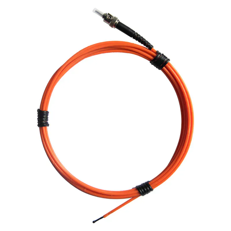
ROTATING MACHINE WINDING PROBE
Measure Winding Temperature Without an Electrical Sensor Signal
The compact fluorescent sensing tip is positioned at a selected winding location while the optical fiber carries the response to a compatible instrument outside the measurement point.
Probe placement, fixing, lead exit and mechanical protection must be designed around the machine. The product is a passive point probe rather than a complete motor monitoring system.
- Motor and generator winding use
- -40 °C to +260 °C configurable range
- 2.5 or 3 mm diameter
- Optical immunity to EMI
Product Overview
The motor winding fiber optic temperature probe is a passive optical component for direct measurement at a selected winding location in motors, generators and related electrical machines. It is intended to bring the sensing point close to the thermal area being assessed rather than infer winding temperature from an external surface.
The final probe location, lead exit and host channel arrangement should be reviewed with the machine design. A compatible fluorescence transmitter or monitoring host is needed to turn the optical response into temperature data and any required alarm or communication output.
MACHINE THERMAL POINT
Selecting a Representative Winding Point
The selected point should correspond to the part of the winding that the project needs to understand or protect.
- Define the winding location before production or rebuild work.
- Use direct point measurement where external measurements are insufficient.
- Plan channel count around the number of required winding points.
ROUTING REVIEW
Planning Lead Exit and Mechanical Protection
The optical route needs to remain practical through the machine structure and into the compatible instrument.
- Confirm the available exit route.
- Avoid mechanical pinch points and unapplication-specific bends.
- Coordinate probe geometry with winding construction.
SHARED MEASUREMENT PRINCIPLE
Passive Point Sensing With a Compatible Instrument
The fluorescent sensing tip measures one selected point. A compatible instrument supplies the optical excitation, processes the returned signal and provides the temperature output. See the standard fluorescence probe for the full measurement principle.
PRODUCT CONSTRUCTION
Motor Winding Probe and Lead-Exit Construction
The product is selected around the winding point, the lead exit and the mechanical path from the machine to the compatible instrument.
Winding sensing point
The fluorescent tip is placed at the selected motor or generator winding location.
Compact optical lead
The optical route is planned through the machine without carrying an electrical temperature signal at the sensing point.
Lead-exit connection
The fiber is brought to the compatible instrument through the approved machine exit path.
PRODUCT SELECTION
When to Choose the Motor Winding Probe
Use this construction for direct winding points where an electrical sensor lead may be undesirable or affected by strong electromagnetic fields.
- Motor stator windings
- Generator winding points
- High-EMI electrical machines
- Development and temperature-rise testing
- Projects with planned optical lead routing
APPLICATION-SPECIFIC ADVANTAGES
Key Probe Features
Winding Point Measurement
The fluorescent tip measures one selected winding location.
EMI-Immune Signal Path
The optical signal does not pick up electromagnetic interference.
Compact Geometry
2.5 or 3 mm configurations suit application-specific winding spaces.
Passive Probe
No powered electronics are installed at the winding point.
Configurable Range
The -40 °C to +260 °C range is confirmed with the final probe.
Machine-Specific Routing
Fixing, lead exit and mechanical protection are application-specific for the motor or generator.
TECHNICAL SPECIFICATIONS
Technical Specifications
Choose the final probe construction and compatible instrument for the application.
Parameters to Confirm Before Ordering
INSTALLATION PLANNING
Plan the Winding Position and Lead Exit
The sensing tip must contact the actual temperature point while the optical route is protected through the equipment.
Target Point
Optical Route
Compatible Instrument
- Select the winding point that represents the required thermal condition.
- Coordinate sensing-tip placement and fixing with the winding process.
- Route the optical lead away from mechanical damage and sharp bends.
- Connect every point probe to a compatible instrument channel.
PRODUCT TO INDUSTRY
Typical Applications
Open the related industry or solution page for application-specific measurement and installation guidance.
RELATED PRODUCTS
Compatible Products for This Application
These products have different roles in the measurement path and are selected according to the installation.
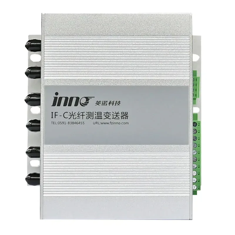
Multi-Channel Fiber Optic Temperature Transmitter
Acquires multiple motor or generator winding points in one central host.
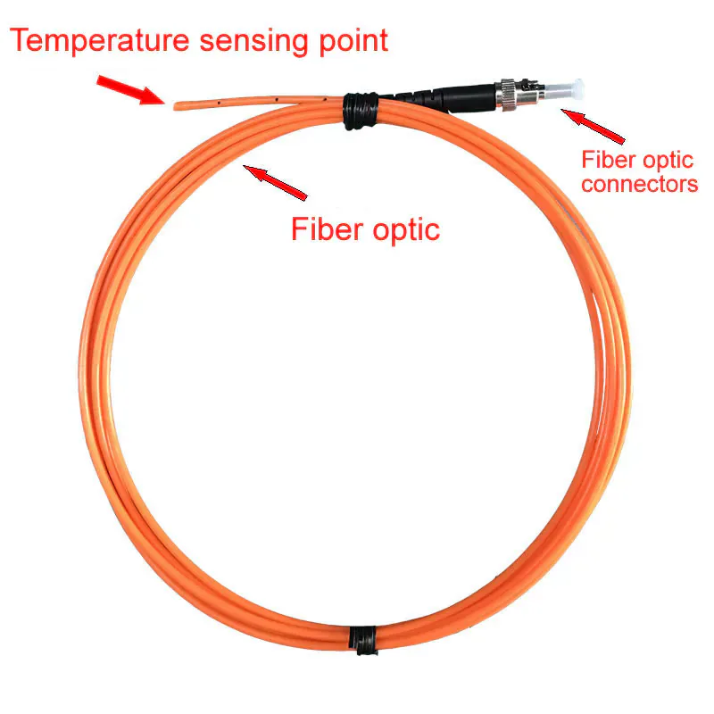
Standard Fluorescent Fiber Optic Temperature Probe
A general-purpose alternative for non-winding point measurements.
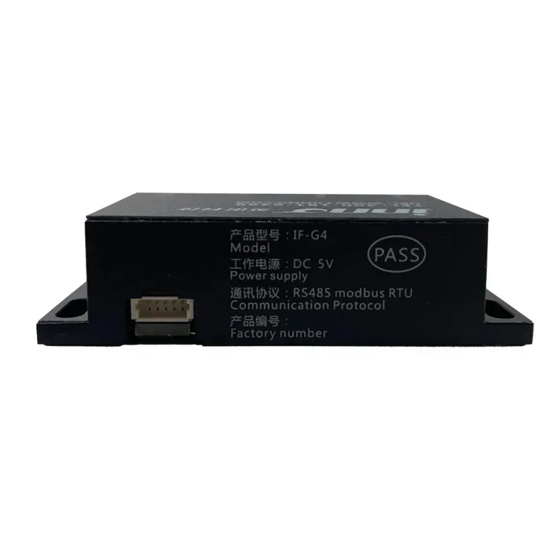
IF-G4 Four-Channel OEM Temperature Module
Supports compact acquisition inside equipment-level designs.
BUYER QUESTIONS
Frequently Asked Questions
Can this probe measure a complete motor winding?
It measures one defined point per probe. Multiple probes and channels are used for multiple winding locations.
Does EMI affect the optical signal?
The optical transmission path is immune to electromagnetic pickup, although the complete installation still requires engineering review.
Can the probe be embedded during winding manufacture?
Embedding and fixing depend on the machine design and should be coordinated with the motor or generator manufacturer.
Does it include alarms or communication?
No. Alarm, RS485 or other outputs are functions of the selected monitoring instrument.
What dimensions are available?
The collected data lists 2.5 mm or 3 mm configurations. Final geometry should be confirmed for the winding space.
What information is needed for selection?
Provide the machine type, winding location, temperature range, lead route, number of points and instrument interface requirements.
PROBE SELECTION SUPPORT
Plan a Motor or Generator Winding Measurement
Share the machine drawing, winding target points, temperature range, probe quantity, lead route and monitoring interface.
- Measurement location
- Required temperature range
- Fiber route and length
Need Help Selecting the Correct Probe Construction?
Share the measurement point, environment and installation constraints with INNO.