
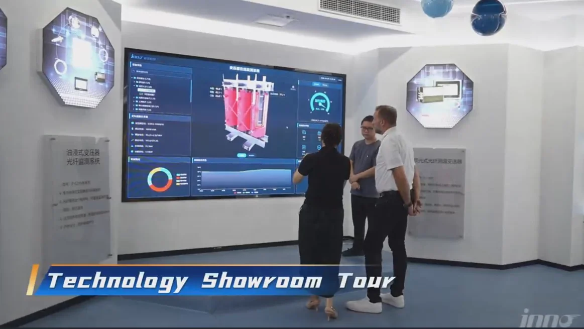
Data center temperature monitoring usually brings to mind room sensors, rack inlet readings and cooling-plant dashboards. Those measurements describe the air around the equipment, not the temperature inside it.
Critical electrical infrastructure produces its own heat. Data center transformers, switchgear and busbar connections carry sustained current, and each contains temperature-sensitive points, such as winding layers and bolted joints, that room air sensors cannot represent. A data center temperature sensor placed in an aisle will not show what is happening inside a transformer enclosure or at a loaded connection.
Equipment-level measurement is the scope covered here. Humidity sensing, HVAC control and rack-level environmental monitoring are left aside. The focus is on measuring defined points in transformers and other electrical equipment, where fluorescence fiber optic sensing becomes relevant and where conventional sensors still do the job in many cases.
Data Center Temperature Monitoring Has Two Different Layers
Searches for data center temp monitoring mostly return environmental products, and that content is useful for what it covers. Two layers need to be separated before any hardware is chosen, because they answer different questions with different sensors.
Facility-Level Environmental Monitoring
Facility-level monitoring tracks room temperature, rack inlet and outlet conditions, airflow and HVAC performance. Data center temperature monitoring sensors for this layer are distributed through white space and cooling plant, and their job is to keep air conditions within the range the IT equipment needs.
INNO does not supply these products, and they are outside INNO's main product scope. For background on sensor types across a facility, see INNO's article on temperature sensors for data centers.
Electrical-Equipment Temperature Monitoring
Electrical-equipment monitoring targets transformers, windings, switchgear, busbar connections and selected high-voltage components. Heat in these locations comes from load current, losses and contact resistance rather than from room conditions. Room air can remain within its normal range while a winding layer or bolted joint runs hotter than the surrounding air, so ambient temperature cannot stand in for equipment temperature.
A data center temperature monitoring system built around this layer places sensors at defined points on the equipment and reads them through a monitoring instrument. Data center thermal monitoring of this kind complements environmental monitoring instead of replacing it: facility sensors show what the air is doing, and equipment sensors show what the electrical hardware is doing. The same measurement-point logic applies in broader industrial temperature monitoring.
Why Transformer Temperature Matters in Data Center Power Infrastructure
Data center transformers sit in the power path between the incoming supply and the distribution that feeds IT and cooling loads. Data center electrical substation transformers handle the first voltage step inside the facility, and the lower-voltage units serving halls or power blocks sit further downstream. Data center substation transformers at either level depend on winding and connection temperatures staying within what the unit was designed for.
Data center loads can be continuous and demanding, which keeps transformers at sustained current for long periods. Internal winding temperature can differ significantly from ambient room temperature, and localized heating may not appear in external measurements. Enclosure and surface readings reflect heat that has reached the outside, which can lag or understate conditions at an embedded winding point.
Equipment-level monitoring supports maintenance and operating decisions by giving engineers temperature data to compare against load, against other units and against earlier behavior. Temperature data does not prevent faults by itself, and it does not guarantee service life. It provides evidence that inspection and operating decisions can use.
For any single data center transformer, permissible temperatures come from the manufacturer's design and applicable project requirements, not from a general figure. Data center transformer monitoring therefore tends to combine the instrumentation the unit already has with direct measurement at selected points where more information is needed. Application details are covered on INNO's transformer temperature monitoring page.
Causes of Overheating in Data Center Dry-Type Transformers
Causes of overheating in data center dry-type transformers fall into three groups: electrical loading, cooling and environment, and local heating at connections. Several can act together, and no single cause explains every temperature rise.
Loading and Electrical Causes
Sustained loading raises winding temperature steadily, and continuous data center load profiles keep that heating in place for long periods. Harmonic-related additional losses can contribute where non-linear loads in the electrical system produce harmonic currents. Whether that matters depends on the load mix and the transformer design. Uneven winding heating can also arise from phase imbalance or construction differences between windings.
Cooling and Environmental Causes
Restricted cooling airflow reduces heat removal from windings and core. Blocked ventilation paths, limited clearance around the unit and poor room ventilation all fall into this category. Fan or forced-air cooling problems matter where such cooling is fitted. Dust, contamination or degradation of cooling surfaces and ducts can reduce heat dissipation over time, and an unsuitable installation environment, such as high ambient temperature, adds to the thermal load. Abnormal operating conditions outside the design basis belong here as well.
Local Heating at Connections
Local connection resistance produces heat at a joint rather than in the winding. Loose or degraded terminals and busbar connections can run hot while winding sensors read normally, which is why connection points are often treated as separate measurement targets.
Interpreting Temperature Symptoms
Different causes can produce similar temperature symptoms. A rising reading may reflect higher load, reduced cooling or a developing connection problem, so temperature data needs to be read together with loading records, cooling status and inspection findings. Data center transformer maintenance can combine periodic inspection with installed sensors for this reason. Further background is available in INNO's article on what causes hot spots in transformers.
Where Temperature Should Be Measured on Data Center Transformers
Sensor location determines what a reading means. Five measurement categories are often confused:
- Ambient temperature: air in the room or enclosure. It describes the environment, not the equipment.
- Surface temperature: outer surfaces of enclosures, cores and accessible components, reachable by contact probes or thermal imaging.
- Winding temperature: conditions inside the coil structure, which may be inferred from other data or measured directly at installed points.
- Defined hot-spot measurement points: locations selected, based on transformer design, where the highest temperatures are expected.
- Terminal and connection temperature: bolted joints and leads, where relevant to the design.
Fluorescence fiber optic probes measure the physical location where the sensing tip is installed. A probe does not search for the hottest point, and it reports the highest winding temperature only if its tip sits at that location. Multiple defined points require multiple probes.
Practical placement depends on the transformer design. Candidates include selected winding positions, expected thermal critical zones identified from the design, selected electrical connections, and locations specified by the transformer manufacturer or engineering team. Access to winding interiors depends on construction, so embedded positions are normally settled with the manufacturer. INNO's articles on where temperature sensors are placed in transformer windings and how many fiber optic temperature sensors are used for transformer windings go into placement and probe count. No fixed number of probes applies to every transformer.
Temperature Monitoring Methods for Data Center Transformers
Four sensing approaches appear in transformer and electrical-equipment monitoring. Each has a place, and the right choice depends on the measurement point.
RTD / PT100 Measurement
RTD and PT100 sensors are established contact sensors with a long record in industrial equipment. Electrical conductors run between the sensing element and the instrumentation, which is acceptable in many conventional locations. Installation position and the electrical environment decide how well they suit a given point, particularly near high voltage or in strong fields where lead routing needs review.
Thermocouples
Thermocouples are simple, familiar and used across many industrial applications. Their metallic conductors can make them less suitable at some high-voltage points or in strong electromagnetic environments, where routing and shielding need attention. In ordinary locations without those constraints they remain a practical choice.
Infrared and Thermal Imaging
Infrared measurement and thermal imaging are non-contact methods for accessible surfaces. Periodic thermographic inspection is valuable for finding hot connections and surface anomalies without installed hardware. Thermal imaging cannot directly measure embedded winding points hidden inside the transformer construction, only what reaches a visible surface. INNO's comparison of point vs non-contact temperature measurement covers the distinction in more detail.
Fluorescence Fiber Optic Temperature Sensing
Fluorescence fiber optic sensing is a point measurement method. Each probe measures one defined location, provides electrical isolation between the sensing point and the instrument, and has high resistance to electromagnetic interference. No metallic electrical sensing conductor is present at the measurement point, which makes it suitable for defined winding and internal points. Multi-channel instruments can read several probes, and the method is useful where direct embedded measurement is required. Technical background is available on INNO's pages for fluorescence fiber optic temperature sensing technology and fiber optic temperature sensors.
Comparison of Temperature Monitoring Methods
| Method | Measurement Type | Typical Measurement Location | Electrical Conductors at Sensing Point | Embedded Point Measurement | Continuous Monitoring | Main Limitation |
|---|---|---|---|---|---|---|
| RTD / PT100 | Contact, resistance-based point measurement | Accessible points, surfaces, installed positions in conventional equipment | Yes | Possible where the sensor is installed during construction | Yes, with installed sensor and instrument | Conductive leads need review near high voltage or strong fields |
| Thermocouple | Contact, junction-voltage point measurement | Process and equipment points in general industrial use | Yes | Possible where the sensor is installed during construction | Yes, with installed sensor and instrument | Low-level signal and metallic conductors need routing and shielding review |
| Infrared / thermal imaging | Non-contact surface temperature | Accessible surfaces, enclosures, visible connections | No | No | Usually periodic surveys | Reads surfaces only; needs line of sight and emissivity attention |
| Fluorescence fiber optic point sensor | Contact point measurement by fluorescence decay time | Defined winding, connection or internal points where the probe is installed | No metallic conductor at the sensing point | Yes, at the points where probes are installed | Yes, with installed probe and instrument | Measures only the points where probes are placed; no line or area coverage |
Method selection depends on the electrical isolation requirement, the measurement location and its access, the surrounding environment, the monitoring architecture, the number of points required, accuracy and response needs, and integration requirements. Many installations use more than one method: thermal imaging for periodic surveys of accessible surfaces, conventional sensors where conditions allow, and fiber optic probes at points where isolation or embedding drives the choice. No row in the table is the right answer for every point.
Direct Winding Hot-Spot Monitoring with Fluorescence Fiber Optic Sensors
Winding temperature can be known in three different ways, and each answers a different question:
- Calculated or inferred winding temperature: derived from a thermal model, load current and a measured reference temperature.
- Surface temperature: measured at accessible outer points and related to the winding only indirectly.
- Direct measurement at an embedded point: a probe installed at a chosen location in the winding structure reports the temperature at that location.
Direct measurement does not replace thermal models or conventional monitoring. It adds actual temperature data from selected locations, which engineers can compare against calculated values and use alongside existing protection and monitoring.
Fluorescence fiber optic probes work through fluorescent sensing material at the probe tip. Fluorescence decay time changes with temperature, and the monitoring instrument analyzes the optical response returned through the fiber. Signals travel as light, and the sensing structure is non-metallic where applicable, so probes can sit near energized windings with electrical isolation and high resistance to electromagnetic interference. More on the measurement approach is available on INNO's fiber optic temperature measurement page.
In data center temperature monitoring programs that include transformers, direct probes supply a layer of data center transformer monitoring that room sensors cannot provide. A temperature sensor for data center electrical rooms and a winding probe serve different purposes, and both can run in the same facility. The probes still measure only their own tip locations, so sensible placement matters more than probe count. See INNO's pages on direct hot-spot monitoring and how transformer winding temperature is measured. Packaged configurations for windings are described in the transformer winding fiber optic temperature monitoring package.
Typical Fiber Optic Monitoring Architecture
Signal flow in a fluorescence fiber optic system follows a short chain:
Fluorescence fiber optic probe
→ Optical fiber / extension connection (where required)
→ Fluorescence temperature transmitter / demodulator
→ Digital temperature data
→ RS485 / Modbus RTU (where applicable)
→ PLC / SCADA or higher-level monitoring platform
Probes sit at the defined measurement points. Optical fiber carries the signal out of the equipment, and an extension connection joins fiber sections where routing requires it. Optical connections use ST connectors on applicable configurations.
Fluorescence temperature transmitters or demodulators convert the optical response into digital temperature values. Multi-channel instruments read several probes in one unit. INNO's multi-channel fiber optic temperature transmitter is an example of this instrument type.
Digital data leaves the instrument over RS485 and Modbus RTU on applicable monitoring instruments, then reaches a PLC, SCADA system or higher-level monitoring platform. INNO's scope is the measurement chain up to digital temperature data. Display, logging and alarm handling at plant level belong to the site's own systems, and integration depends on site architecture and interface requirements. INNO does not provide a DCIM platform. Pages on fiber optic temperature monitoring systems and PLC and SCADA system integration cover the integration side.
Multi-Point Temperature Monitoring for Data Center Electrical Equipment
Multiple defined measurement points are often needed because electrical equipment heats unevenly. A transformer can have several winding positions of interest, and connection points sit apart from the windings. Typical monitored locations include:
- Transformer winding points
- Transformer connections
- Switchgear connections
- Busbar bolted joints
- Selected high-voltage electrical equipment points
One probe equals one point, and multiple probes provide multiple independent points. Fluorescence point sensing does not provide continuous cable temperature monitoring, and no value exists between probe locations. Temperature at a point without a probe is unknown.
Multi-channel instruments simplify centralized acquisition: probes from several locations connect to one instrument, and one communication link carries all readings. Channel count follows the number of defined points.
For configuration details, see INNO's page on multi-point temperature monitoring. Switchgear applications are covered under switchgear temperature monitoring, and the switchgear fiber optic temperature monitoring system page describes the packaged configuration. Bolted joints use dedicated probe structures, such as the busbar bolt connection fiber optic temperature probe.
Typical INNO Fluorescence Fiber Optic Monitoring Parameters
Typical values depend on probe and system configuration. The table below lists a typical INNO fluorescence fiber optic configuration, and the standard fluorescence fiber optic temperature probe page gives product-level detail.
| Parameter | Typical / Configuration-Dependent Value |
|---|---|
| Measurement principle | Fluorescence decay time |
| Temperature range | −40 °C to +260 °C (typical) |
| Accuracy | ±0.5 °C to ±1 °C depending on configuration |
| Resolution | 0.1 °C |
| Response | <1 s for standard configurations |
| Probe diameter | 2–3 mm, configurable |
| Fiber length | Configurable according to application requirements |
| Electrical insulation | >100 kV for applicable configurations |
| Connector | ST |
| Channel options | Single-channel and multi-channel |
| Communication | RS485 / Modbus RTU for applicable monitoring instruments |
Values in the table describe typical configurations and should not be treated as universal specifications for every INNO product.
Choosing a Data Center Temperature Monitoring System for Transformers
Selection works best as an engineering workflow in which each decision narrows the next.
Define the Actual Measurement Points
Transformer type comes first, since dry-type and oil-immersed units differ in construction and access. Winding locations follow, with accessible points separated from embedded ones. Point count comes from that list. Whether direct winding measurement is required at all depends on the monitoring the unit already has and on the information the project needs.
Match Sensor Technology to the Electrical Environment
Voltage level, electromagnetic interference, isolation requirements and strong fields all influence sensor choice. Sensor materials and cable routing matter as well, since conductive leads run through the same space as energized parts. Where measurement points sit near high voltage, review INNO's guidance on high-voltage equipment temperature monitoring.
Determine Channel Count and System Expansion
Channel count should follow the defined measurement points. Spare capacity can be added according to project requirements, for example for points added during commissioning. No universal channel number applies, because a project with a handful of winding points differs from one that includes switchgear connections across several rooms.
Define Data and Alarm Integration
Decisions here cover whether a local monitoring instrument is needed, whether RS485 and Modbus RTU suffice, and which PLC or SCADA system receives the data. Alarm strategy should come from equipment design and operating requirements. Thresholds are set per project and are not generic values.
Review Installation Requirements Before Ordering
Probe structure, fiber length, routing, connectors and installation access all need confirmation against the transformer construction and the system interface. Fiber route lengths from probe to instrument decide the fiber length order. INNO's article on how to choose a fiber optic temperature monitoring system goes through these points in more detail.
Data Center Temperature Sensors: When Fiber Optic Sensing Is the Better Fit
Data center temperature sensors for electrical equipment fall into the fiber optic category when specific conditions apply. Fluorescence fiber optic sensing is worth considering when:
- The measurement point sits near high voltage
- Electrical isolation is required
- Embedded winding measurement is needed
- Strong electromagnetic fields complicate metallic sensor wiring
- Multiple defined points require centralized optical measurement
- Conventional surface measurements do not provide the internal temperature information needed
Fiber optic sensing is not automatically the best choice elsewhere. Normal room temperature monitoring, humidity monitoring, low-cost general HVAC sensing and ordinary accessible ambient points are better served by conventional environmental sensors. Fluorescence probes add value where isolation, embedding or field conditions drive the requirement, and they add cost and complexity where those conditions are absent.
Two INNO articles cover the electrical side: why fiber optic temperature sensors are used near high voltage and temperature measurement in strong electromagnetic fields.
Transformer Monitoring vs General Data Center Environmental Monitoring
| Monitoring Layer | Typical Measurement Target | Typical Sensor Approach | Primary Purpose | INNO Relevance |
|---|---|---|---|---|
| Room / HVAC environment | Room air, supply and return air | Environmental air sensors | Keep air conditions within the range required by IT equipment | Outside INNO's product scope |
| Rack / aisle environment | Rack inlet and outlet air, aisle conditions | Rack-mounted or aisle air sensors | Confirm cooling delivery to IT equipment | Outside INNO's product scope |
| Transformer / electrical equipment | Enclosures, surfaces, connections, switchgear and busbar joints | RTD, thermocouple, infrared or fiber optic, depending on the point | Track equipment temperature under load | INNO's focus at selected electrical points |
| Embedded winding / defined hot-spot points | Selected internal winding locations | Fluorescence fiber optic point probes | Obtain direct temperature data at chosen points | INNO's core application |
Choosing a data center temperature monitor or a data center temperature monitoring device starts with deciding which row of this table the measurement belongs to. Data center temp monitoring for room air and racks uses a different product class from monitoring inside a transformer, and combining the two layers gives a more complete picture than either alone.
Practical Questions for a Data Center Transformer Monitoring Project
RFQ and engineering discussions move faster when the transformer side is defined first. Transformer type and construction, dry-type or oil-immersed, set what is physically reachable, and the number of transformers sets the system scale. Intended measurement locations then turn into a count of temperature points.
Probe structure and fiber length depend on those locations and on routing from each transformer to the instrument. Expected temperature range, accuracy requirement and required instrument channels come from the monitoring objective. Whether RS485 or Modbus RTU communication is needed, and which PLC or SCADA interface receives the data, belong in the same conversation. Installation constraints, such as access during manufacture or outage windows for existing units, complete the picture.
Engineers who bring a point list, a one-line description of each transformer and the target plant interface can usually get a specific configuration response with little back-and-forth.
Building the Right Temperature Monitoring Architecture for Data Center Transformers
Environmental monitoring alone does not show every internal electrical-equipment temperature condition. Room and rack sensors describe air, while transformers, switchgear and busbar connections have their own heat sources and their own critical points.
Transformer and winding monitoring depends on measurement points chosen according to equipment design, with the manufacturer or engineering team defining where temperatures matter. Conventional sensors remain suitable at many of those points. Fluorescence fiber optic sensors are useful where direct point measurement, electrical isolation and high resistance to electromagnetic interference are required, and they measure only the locations where probes are installed.
Channel count and communication interfaces should follow the project: the number of defined points, the instrument configuration, and the RS485, Modbus RTU, PLC or SCADA requirements at the site.
Project details such as transformer type, intended measurement points and plant interface can be sent to contact INNO for a configuration review.