
Fiber optic temperature sensors are used for high-voltage temperature measurement because the sensing path is electrically isolated and immune to electromagnetic interference. The probe can measure temperature at a selected physical point near energized equipment while the monitoring instrument remains electrically separated from the measurement location.
This is particularly useful in transformers, switchgear, busbars, generators, power electronics, high-voltage test equipment, RF systems and other environments where conductive sensor wiring may introduce insulation, grounding, interference or routing challenges. This guide focuses on fluorescence-based point fiber optic temperature sensing, where one probe measures one defined physical temperature point and the optical fiber carries no electrical measurement signal.
The main value of fiber optic temperature sensing in these environments is not simply higher accuracy. The core advantages are electrical isolation, a non-conductive optical path, EMI immunity, direct point sensing, and the ability to place sensing probes in electrically difficult locations.
Key Takeaways
- Fiber optic probes provide an electrically isolated temperature measurement path.
- Optical sensing is immune to electromagnetic interference along the measurement path.
- A point fiber optic probe measures the actual temperature at one selected physical location.
- The monitoring instrument can be positioned away from the high-voltage sensing point.
- Multiple probes can be connected to a multi-channel temperature monitoring system.
- Fiber optic sensors are especially useful where electrical isolation, EMI immunity or direct temperature measurement is required.
Why Is Temperature Measurement Difficult Near High Voltage?
Temperature measurement near high-voltage equipment involves practical challenges such as large electrical potential differences, insulation requirements, electromagnetic fields, switching transients, grounding considerations, conductive wiring routes and restricted sensor placement.
High voltage does not make temperature impossible to measure - conventional sensors can still be used, but their design and installation require additional consideration. The challenge is not temperature itself. The challenge is obtaining a reliable temperature signal while maintaining the required electrical isolation and measurement integrity.
How Does Electrical Isolation Help High-Voltage Temperature Measurement?
A fiber optic probe uses optical transmission rather than conductive electrical measurement wiring. This means there is no electrical measurement conductor running from the sensing point to the instrument, the electrical potential at the measurement point is not carried back through the optical fiber, and the monitoring electronics can be located at a different physical position.
This does not mean zero electrical risk or that all high-voltage hazards are eliminated. It means the optical sensing path helps simplify electrical isolation of the temperature measurement itself.
Why Is EMI Immunity Important?
High-voltage equipment can generate strong electromagnetic fields and switching interference. Electrical sensor circuits may require shielding, grounding, careful cable routing and signal conditioning to maintain a clean measurement signal in this environment.
A fiber optic sensing path is not affected by electromagnetic interference in the same way as conductive electrical signal wiring. This EMI immunity applies to the optical measurement path - it does not mean electromagnetic interference changes the actual temperature being measured; it means electrical signal wiring is more exposed to interference than an optical path.
How Does a Fiber Optic Temperature Sensor Measure Near Energized Equipment?
The measurement sequence is straightforward: the probe tip is placed at the selected measurement point, temperature affects the fluorescent sensing material, the optical signal travels through the fiber, and the monitoring instrument converts the optical response into temperature data.
This is point temperature measurement. One probe corresponds to one defined sensing point, not the surrounding equipment as a whole.
Fiber Optic vs PT100 vs Thermocouple in High-Voltage Environments
| Measurement Method | Signal Path | Electrical Isolation | EMI Consideration | Typical High-Voltage Use |
|---|---|---|---|---|
| Fiber Optic Temperature Sensor | Optical | Inherent optical isolation | High EMI immunity | Direct point measurement near energized equipment |
| PT100 / RTD | Electrical resistance signal | Requires appropriate isolation and wiring design | Shielding / grounding may be required | Common in conventional industrial and transformer applications |
| Thermocouple | Electrical voltage signal | Requires appropriate isolation | Can be affected by electrical noise depending on installation | Widely used in industrial process temperature measurement |
| Infrared | Non-contact optical | No wired contact with measurement point | Not affected through conductive wiring | Useful for visible / accessible surfaces |
When Is Fiber Optic Temperature Measurement More Practical?
Fiber optic sensing tends to be more practical when the sensor must be close to an energized conductor, when electrical isolation is difficult to achieve with conductive wiring, when strong EMI or RF fields are present, when direct internal temperature is needed, when monitoring electronics need to remain farther away, when several isolated temperature points must be monitored, or when conventional electrical sensor wiring is difficult to route.
It is selected because of the measurement environment, not simply because it is a newer sensor technology.
High-Voltage Transformer Winding Temperature Measurement
Transformer windings are one of the most important applications for fiber optic temperature sensing. Probes can be embedded at selected winding temperature locations during transformer manufacturing for direct winding temperature measurement, covering selected hot-spot locations, multiple winding heights, and HV / LV winding monitoring where required.
The probe measures only the selected physical point - it does not automatically find the transformer hot spot. Placement logic and channel planning for this application are covered in more detail in related articles on where fiber optic temperature sensors are placed in transformer windings and how transformer winding temperature is measured.
High-Voltage Switchgear and Busbar Temperature Measurement
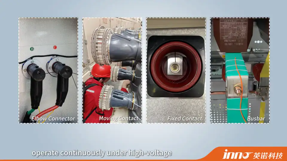
Typical switchgear measurement points include busbar joints, cable terminations, contacts, connection points and other selected energized conductors. Optical temperature probes can be used where electrical isolation is important and the sensing point is difficult to connect using conventional electrical measurement wiring.
Not every switchgear installation requires fiber optic sensing - the decision depends on the specific connection point and the electrical isolation requirements of that installation.
Generator and Motor Winding Temperature Measurement
Large generators and motors present strong electromagnetic fields, significant winding current and specific electrical insulation requirements. Fiber optic sensing can provide isolated point temperature measurement at selected winding or stator locations without introducing conductive wiring into the electromagnetic environment.
Measurement point selection still depends on the specific machine design rather than a fixed location that applies to every generator or motor.
High-Voltage Test Equipment and Laboratory Measurement
In high-voltage testing, the probe can remain close to the test object while the monitoring instrument is physically positioned farther away. This is useful in insulation testing, electrical equipment testing, high-voltage research, test benches and dielectric test environments.
Specific safe distances and test voltage standards should be defined according to the applicable test procedures and facility requirements, not assumed from a general reference.
Power Electronics, IGBT and SiC Temperature Measurement
Power electronics testing can involve high switching voltage, fast electrical transients, strong EMI and electrically active devices. A fiber optic temperature probe can be used for direct point temperature measurement at a device surface, module, or selected test point on a power semiconductor assembly where electrical isolation is required.
Measurement is limited to the location where the probe tip is physically installed - it should not be assumed to represent an internal junction temperature unless the sensor placement specifically supports that measurement point.
RF and Microwave Temperature Measurement
RF and microwave environments are not always classified as conventional power-grid high voltage, but they share the same relevant characteristics of electrical isolation and EMI immunity. A fiber optic probe can measure temperature inside or near RF / microwave fields while the monitoring instrument remains outside the active field where required.
Typical High-Voltage Temperature Measurement Applications
| Application | Typical Measurement Point | Why Fiber Optic Sensing May Be Used |
|---|---|---|
| Transformer | Winding / selected hot spot | Direct internal measurement and electrical isolation |
| Switchgear | Busbar / cable termination / contact | Isolated measurement near energized components |
| Generator | Winding / stator | Strong electromagnetic field |
| High-Voltage Test Bench | Test object | Instrument can remain away from energized area |
| Power Electronics | Module / selected device location | Fast switching and EMI environment |
| RF / Microwave Equipment | Internal test point | Optical sensing in strong RF field |
| Laboratory Equipment | Selected electrically active test point | Flexible electrically isolated measurement |
These are application examples rather than mandatory sensor configurations.
How Far Can the Monitoring Instrument Be from the High-Voltage Measurement Point?
Fiber length determines the physical routing distance between the sensing point and the monitoring instrument. Typical fiber optic probe configurations support approximately 0-20 m depending on probe structure and project requirements, and 3-5 m can be a practical starting reference for many equipment applications. High-voltage testing may require longer routing depending on the layout.
A longer fiber is not inherently safer - fiber length should follow the actual routing requirement and instrument location. Selection considerations are covered in a dedicated guide on choosing the right fiber length for a fiber optic temperature sensor.
Can Multiple High-Voltage Temperature Points Be Monitored?
Yes. One point probe normally corresponds to one measurement channel, and a multi-channel system can be used for multiple transformer winding points, multiple switchgear connections, several test objects, or multiple power-electronics test points.
Some monitoring instruments support special configurations of approximately 1-64 channels depending on instrument design and project requirements, though not every model supports the same channel range. Channel planning is discussed further in a related article on how many channels are needed for fiber optic temperature monitoring.
Does High Voltage Affect Fiber Optic Temperature Measurement Accuracy?
High voltage itself is not normally the parameter used to determine temperature measurement accuracy in an optical point sensing system. Accuracy is primarily related to probe design, the sensing element, the monitoring instrument, calibration and system configuration, thermal contact, and application conditions.
The advantage of fiber optic sensing in high-voltage environments is mainly electrical isolation and immunity to electromagnetic interference, rather than a direct effect of voltage on accuracy.
Does EMI Affect Fiber Optic Temperature Sensors?
The optical sensing path is inherently immune to electromagnetic interference. However, the overall system still includes electronic components such as the monitoring instrument, power supply and communication wiring, which should be installed according to normal engineering practice for power, grounding and communication.
This means the optical measurement path itself resists EMI, but it does not mean the entire installation is immune to every form of interference at every point in the system.
What Outputs Can a High-Voltage Temperature Monitoring System Provide?
Depending on the selected monitoring instrument, available outputs can include local temperature display, RS485, Modbus RTU, 4-20 mA, alarm relay output, and integration with PLC or SCADA systems.
Available interfaces depend on the specific monitoring instrument selected - not every model supports every output, and independent 4-20 mA per channel should only be assumed where the product specifically offers it.
How to Choose a Fiber Optic Temperature Sensor for High-Voltage Measurement
Practical selection factors include:
- Temperature range
- Measurement-point location
- Probe diameter / structure
- Fiber length
- Number of sensing points
- Number of monitoring channels
- Electrical environment
- Monitoring instrument
- Required communication output
- Installation route
Typical probe configurations offer a temperature range of approximately -40 to 260 C, accuracy of approximately +/-0.5 to +/-1 C, response of under 1 second, a probe diameter of approximately 2-3 mm, and a fiber length of approximately 0-20 m depending on configuration. These are typical reference values rather than fixed specifications for every product.
Fiber Optic vs Non-Contact Infrared Measurement Near High Voltage
Infrared measurement is non-contact, useful for accessible surfaces, requires no sensor wiring at the measurement point, and depends on line of sight and surface measurement conditions. Fiber optic measurement uses direct contact or embedded point sensing, can measure internal or enclosed locations where probe access is available, is suitable for continuous point monitoring, and provides electrically isolated optical sensing.
Infrared is not inaccurate - it serves a different measurement purpose, particularly for accessible surfaces where continuous embedded sensing is not practical.
What Information Is Needed Before Selecting a High-Voltage Temperature Sensor?
- Equipment type
- Voltage environment
- Measurement point
- Surface or internal measurement
- Required temperature range
- Expected operating temperature
- Probe dimensions
- Fiber length
- Number of sensing points
- Number of monitoring channels
- Monitoring instrument location
- EMI / RF environment
- Required communication interface
- PLC / SCADA requirement
- Alarm output requirement
- Installation space
- Connector requirement
Common High-Voltage Temperature Measurement Misunderstandings
High voltage itself changes the temperature reading. High voltage and EMI mainly create measurement-system challenges; they do not directly change the physical temperature being measured.
Fiber optic sensors are selected only because they are more accurate. Electrical isolation and EMI immunity are often the main reasons, not accuracy alone.
PT100 and thermocouples cannot be used near high voltage. They can be used successfully when insulation, shielding, grounding and system design are appropriate.
A single fiber optic probe can measure an entire transformer or busbar system. One point probe measures one defined location, not the whole system.
The monitoring instrument must be installed beside the sensing point. The optical fiber allows the instrument to be positioned separately according to the required routing and system design.