
Fiber optic temperature sensors are normally placed at selected winding locations where the highest operating temperatures or thermal hot spots are expected. The exact positions depend on transformer design, winding geometry, cooling arrangement, conductor current distribution, insulation structure and the transformer's thermal design.
For oil-immersed transformers, fiber optic probes are commonly embedded or positioned within the winding structure during transformer manufacturing, close to selected conductor or winding hot-spot locations. For dry-type transformers, probes may be positioned at selected winding locations or within accessible winding structures depending on the transformer construction.
This guide focuses on fluorescence-based point fiber optic temperature sensing, where a single probe measures one defined temperature point and the optical fiber carries the signal away from the winding to a monitoring instrument. Placement is never a fixed, universal position - it is defined by the transformer designer or manufacturer based on thermal design and winding structure.
Key Takeaways
- Fiber optic probes are placed at selected predicted winding hot-spot locations, not at a single universal position.
- Sensor placement is transformer-design-specific and depends on winding geometry and cooling.
- Oil-immersed transformer probes are typically installed during manufacturing, before the winding assembly is completed.
- Multiple probes can be positioned at different winding heights, phases or winding sections.
- HV and LV winding sensor requirements depend on the transformer's thermal design, not a fixed rule.
- One point fiber optic probe measures one defined temperature point, not the whole winding.
- Final probe placement should be confirmed by the transformer manufacturer or design engineer.
Where Are Fiber Optic Temperature Sensors Typically Placed in Transformer Windings?
Common transformer winding temperature sensor placement locations can include selected winding hot-spot regions, locations near conductors expected to operate at higher temperature, upper winding regions where thermal conditions may be more severe in some designs, and selected middle or lower winding positions where thermal verification is needed. Sensors may also be placed in HV winding locations, LV winding locations, or specific winding sections identified by thermal calculations or design experience.
In many transformer designs, higher winding regions may be important because of the interaction between losses, oil flow and cooling, but the actual hot-spot location varies with winding and cooling design. There is no single position that applies to every transformer, so placement should always be based on the specific thermal design rather than a generic rule.
Why Is the Sensor Usually Placed Near a Winding Hot Spot?
One of the main values of direct winding temperature measurement is that it captures the actual physical temperature at a selected predicted hot-spot region, rather than an estimated value. The winding hot-spot location is influenced by current density, conductor losses, stray losses, cooling effectiveness, oil circulation, winding geometry and insulation structure.
Because of this, the sensor location should represent a meaningful thermal measurement point, not simply an easy-to-reach location. Selecting a sensing point that corresponds to the transformer's expected thermal behavior is what makes the measurement useful for winding hot-spot monitoring.
Are Sensors Always Installed at the Top of the Winding?
No. In some transformer designs, the upper winding region may be an important temperature area, but the hot-spot location is not universally fixed at the top of the winding. The actual location depends on the winding type, oil flow, cooling ducts, conductor arrangement, load distribution and the transformer's cooling method.
Some transformer manufacturers therefore place probes at several winding heights rather than relying on a single upper-winding measurement point, which allows the temperature distribution along the winding to be observed rather than assumed.
Should Sensors Be Installed in the HV Winding, LV Winding, or Both?
It depends on transformer design and monitoring objectives. A monitoring system may cover the HV winding, the LV winding, both windings, selected phases, or selected winding sections, depending on the calculated thermal behavior, winding current, conductor geometry, cooling conditions, transformer rating and monitoring objective.
There is no general rule stating that the HV winding or the LV winding is always hotter - this varies by transformer design, and the decision should follow the specific thermal analysis for that unit.
Why Are Multiple Sensor Positions Used?
A single temperature point cannot represent the condition of an entire winding. Multiple sensing points are used to cover different phases, different winding heights, HV and LV winding locations, different thermal zones, and selected hot-spot locations identified during transformer design.
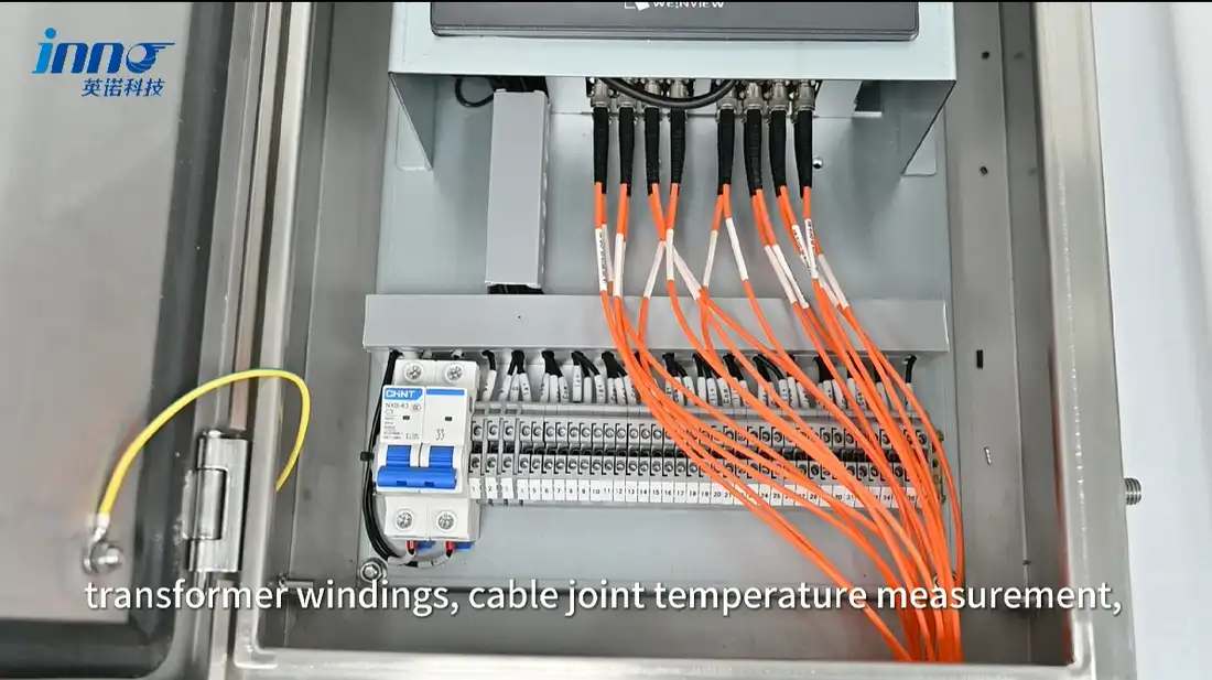
This is the basis of multi-point temperature monitoring, where each point fiber optic probe normally corresponds to one measurement channel on the multi-channel temperature monitoring instrument, allowing several winding locations to be observed at the same time.
Typical Fiber Optic Sensor Locations in a Transformer
| Measurement Area | Why It May Be Monitored | Selection Consideration |
|---|---|---|
| Upper Winding Region | Potential high-temperature region in some designs | Cooling and winding design |
| Middle Winding Region | Temperature profile verification | Winding geometry and oil flow |
| Lower Winding Region | Thermal distribution monitoring | Cooling path and winding structure |
| HV Winding | Selected electrical / thermal monitoring point | Transformer thermal design |
| LV Winding | Selected thermal monitoring point | Current and winding construction |
| Different Phases | Compare phase temperature behavior | Transformer phase arrangement |
| Multiple Winding Sections | Build a more complete thermal profile | Available monitoring channels |
These are possible measurement locations, not mandatory sensor positions for every transformer.
Where Is the Probe Tip Positioned?
The sensing tip generally needs to be positioned close to the selected winding measurement location. Depending on the transformer design, this may be between winding conductors and insulation structures, within a spacer or designated sensor channel, adjacent to a selected conductor, or within a designed winding measurement location.
Specific mounting distances, pressing methods and insulation clearances are determined by the transformer manufacturer as part of the winding design. The optical fiber itself is routed away from the sensing point through a protected path designed for the winding structure, which is discussed further in how to choose the right fiber length for a fiber optic temperature sensor.
When Are Fiber Optic Sensors Installed in Transformer Windings?
For oil-immersed transformer winding applications, probes are generally integrated during transformer manufacturing or winding assembly. Once the winding is completed, insulation is assembled and the tank is closed, internal winding access is extremely limited.
Because of this, sensor locations and fiber routing are normally planned during the transformer design and manufacturing stage, rather than decided later on site.
Can Fiber Optic Sensors Be Added to an Existing Transformer?
This depends on what is being measured. For internal winding temperature measurement, sensors generally cannot be simply added to the winding of an already-completed oil-immersed transformer, because internal winding sensor placement requires physical access to the winding structure during assembly.
Retrofit transformer monitoring, on the other hand, may cover accessible temperature points such as top oil or other accessible equipment temperatures. Retrofit monitoring of accessible points should not be confused with embedded internal winding sensing, which is planned at the manufacturing stage.
Sensor Placement in Oil-Immersed Transformers
In oil-immersed transformers, the sensing probe should be positioned at locations selected during transformer thermal design, taking into account winding cooling ducts and oil flow, while the optical fiber is routed toward a suitable transformer feedthrough and then to the external monitoring instrument.
This approach to direct winding temperature measurement is described in more detail in how is transformer winding temperature measured, and the overall application is covered on the transformer temperature monitoring page.
Sensor Placement in Dry-Type Transformers
Dry-type transformers are not identical to oil-immersed transformers in terms of sensor placement. Depending on the transformer structure, probes may be positioned on a phase winding, at the coil surface, within an internal winding region, at a selected conductor or winding section, or near the temperature controller position.
Fiber optic probes can be positioned at selected winding locations where direct optical sensing, electrical isolation or EMI immunity are useful. PT100 sensors are commonly used in many dry-type transformer temperature control systems, while fiber optic sensors can be considered where direct optical sensing, electrical isolation or special high-voltage measurement conditions are required.
How Many Fiber Optic Sensors Are Needed in Transformer Windings?
The required sensor quantity depends on the number of phases, the number of windings being monitored, the number of winding heights of interest, the monitoring objective, transformer size, thermal design, and the available monitoring channels.
Oil-immersed transformer fiber optic systems often use multi-channel configurations such as 6, 8, 9, 12 or 16 channels, while dry-type transformer fiber optic monitoring may commonly use 3, 4, 6 or 7 channels. These are common system configurations, not mandatory probe counts - the actual sensor count should match the actual measurement points defined for the specific transformer.
Does Each Sensor Need Its Own Monitoring Channel?
Yes. In a point fiber optic temperature monitoring system, each active sensing probe normally uses one measurement channel. For example, six selected winding measurement points require six active sensor channels on the monitoring instrument.
If future expansion is expected, a monitoring instrument with higher channel capacity can be selected in advance. Channel planning is covered in more detail in how many channels do you need for fiber optic temperature monitoring.
How Does Transformer Design Affect Sensor Placement?
Sensor placement is directly influenced by several aspects of transformer design, including:
- Winding geometry
- Disc, layer or foil winding construction
- Cooling ducts and oil flow direction
- Insulation design
- Conductor arrangement
- HV / LV winding location
- Phase arrangement
- Expected thermal distribution
Sensor placement should follow transformer thermal design rather than a generic placement diagram applied to every unit.
Direct Winding Temperature Measurement vs Estimated Winding Temperature
| Method | What It Represents | Typical Use |
|---|---|---|
| Embedded Fiber Optic Sensor | Actual temperature at selected physical winding point | Direct winding temperature monitoring |
| Winding Temperature Indicator | Calculated / simulated winding temperature based on oil temperature and load, depending on system design | Traditional transformer monitoring |
| Resistance Method | Average winding temperature | Transformer testing |
| Oil Temperature Sensor | Transformer oil temperature | Oil thermal monitoring |
A fiber optic probe measures the temperature at the exact selected sensing point. It does not represent a whole-winding average temperature, and it does not automatically report the maximum temperature everywhere in the winding.
What Makes a Good Winding Temperature Measurement Point?
A good winding temperature measurement point should represent a thermally important winding location, correspond to transformer thermal analysis or design experience, be mechanically suitable for sensor integration, allow protected fiber routing, and provide useful temperature information for ongoing monitoring.
Common Sensor Placement Mistakes
1. Assuming every transformer has the same hot-spot location. Hot-spot position varies by winding and cooling design, so it should not be copied from another project.
2. Placing the sensor only where installation is easiest. A convenient location does not always represent a thermally meaningful point.
3. Using one measurement point to represent every winding and phase. A single sensor cannot describe the condition of the whole transformer.
4. Selecting probe locations without considering fiber routing. The sensing point must also allow a practical and protected path to the feedthrough.
5. Choosing sensor quantity before defining the required winding measurement points. Channel count should follow the measurement plan, not the other way around.
What Information Is Needed Before Selecting Sensor Positions?
- Transformer type
- Oil-immersed or dry-type
- Transformer rating
- Number of phases
- HV / LV winding structure
- Winding construction
- Expected hot-spot region
- Number of measurement points
- Measurement heights
- Probe quantity
- Fiber routing
- Fiber length
- Feedthrough location
- Monitoring instrument location
- Required channel quantity
- Required communication output