
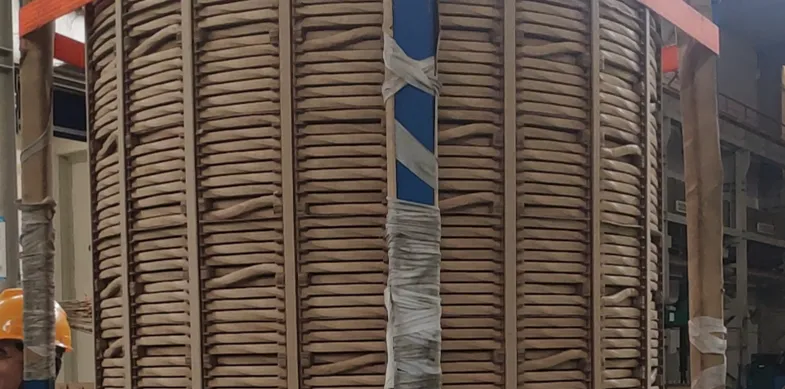
Transformer winding temperature can be measured either directly at selected winding locations or estimated indirectly from oil temperature, load current and thermal behavior. Traditional winding temperature indicators and thermal models generally estimate winding or hot-spot temperature. Embedded temperature probes, including fiber optic point sensors, can measure temperature directly at selected locations inside the winding structure.
Different methods answer different questions: average winding temperature, estimated winding temperature, estimated hot-spot temperature, and actual temperature at a selected winding point. These four concepts are related, but they are not the same measurement.
Key Takeaways
- Transformer winding temperature can be measured directly or estimated indirectly.
- A traditional WTI generally represents winding temperature using oil temperature and load-related heating rather than measuring the conductor directly.
- Resistance measurement provides average winding temperature and is mainly useful during transformer testing rather than continuous internal hot-spot monitoring.
- Embedded fiber optic probes can measure temperature directly at selected winding locations.
- One point probe measures one defined location, so multiple probes are used when several winding positions need simultaneous monitoring.
- Oil-immersed and dry-type transformers require different sensor placement and monitoring arrangements.
Transformer Winding Temperature Measurement Methods at a Glance
| Method | Direct or Indirect | What It Measures | Online Monitoring | Typical Use |
|---|---|---|---|---|
| Embedded Fiber Optic Probe | Direct | Temperature at selected internal winding point | Yes | Hot-spot / internal winding monitoring |
| Winding Temperature Indicator (WTI) | Indirect | Simulated or indicated winding temperature | Yes | Traditional transformer monitoring / cooling control |
| Thermal Model | Indirect | Calculated winding hot-spot temperature | Yes | Transformer monitoring systems |
| Resistance Method | Indirect / average temperature derived from resistance | Average winding temperature | Usually test-based | Temperature-rise tests / transformer testing |
| RTD / PT100 | Direct at sensor location where design allows | Selected physical point | Yes | Common in some dry-type transformer arrangements |
| Infrared | Direct surface measurement | Accessible external surface | Yes / periodic | Surface inspection, not internal winding hot spot |
What Does "Transformer Winding Temperature" Actually Mean?
Average Winding Temperature
The overall average temperature of the winding, which can be derived from methods such as winding resistance change.
Winding Hot-Spot Temperature
The localized position within the winding expected to reach the highest temperature, or a location of particular thermal interest — a key value in transformer thermal monitoring.
Measured Point Temperature
The actual temperature at the physical location where a sensor is installed.
Calculated / Indicated Winding Temperature
A value derived or simulated from oil temperature, load current and a thermal model.
These values are related, but they are not the same measurement.
Method 1: Winding Temperature Indicator (WTI)
Does a WTI directly measure winding temperature? In many traditional transformer designs, no.
A traditional WTI typically uses a temperature bulb or sensor related to oil temperature, combined with a current transformer input and a heating element or compensation mechanism, to simulate the winding temperature rise relative to the oil temperature. Modern electronic devices may instead use a current input and measured top-oil temperature to calculate winding temperature electronically.
WTI outputs are commonly used for local temperature indication, alarms, fan control, pump control and transformer cooling control. A WTI does not necessarily represent the actual hottest conductor point in the winding.
Method 2: Transformer Thermal Models
Modern transformer monitoring systems can estimate winding hot-spot temperature using measured operating data and a thermal model. Typical inputs may include top-oil temperature, load current, transformer loading and cooling status, along with transformer-specific thermal parameters.
Outputs may include a calculated winding temperature, an estimated hot-spot temperature, or thermal loading information.
This approach has practical advantages: it does not require an internal electronic sensor at every location, it supports continuous online monitoring, and it can integrate into transformer condition monitoring systems. However, a calculated hot-spot temperature remains a model output rather than a direct physical measurement at the winding point.
Method 3: Winding Resistance Measurement
Copper or aluminum winding resistance changes with temperature. By comparing measured winding resistance with a reference value, average winding temperature can be determined.
This method is commonly used for factory testing, temperature-rise testing, and commissioning or diagnostic testing where applicable.
An important distinction: resistance measurement gives an average winding temperature, not the actual local winding hot spot. The method is valuable for transformer testing but is not normally used as continuous online point-temperature monitoring inside an energized winding.
Method 4: Direct Measurement with Fiber Optic Temperature Probes
This guide refers to fluorescence-based point fiber optic temperature probes for direct winding measurement. For transformers designed with embedded optical probes, temperature can be measured directly at selected winding locations.
The typical signal path is: fiber optic temperature probe → optical fiber → transformer feedthrough / routing → temperature transmitter or monitoring instrument. The sensing tip is positioned at a selected winding location during transformer manufacturing or winding assembly.
| Parameter | Typical Value |
|---|---|
| Temperature Range | -40 to 260 °C |
| Accuracy | ±0.5 to ±1 °C |
| Response Time | <1 s |
| Probe Diameter | Approximately 2–3 mm |
| Fiber Length | Commonly configured according to transformer dimensions and instrument position |
Exact specifications depend on probe configuration.
Why Fiber Optic Sensors Are Used Inside Transformer Windings
- Electrically isolated sensing path
- Immunity to electromagnetic interference
- Small probe structure suited to compact winding spaces
- Direct measurement at selected winding positions
- Optical fiber can route from the internal sensing point to an external monitoring instrument
- Multiple sensing points can be monitored simultaneously
Where Are Fiber Optic Temperature Probes Installed?
Probe locations are determined during transformer design based on expected thermal behavior and the measurement objective. Common areas of interest can include selected winding hot-spot locations, winding sections expected to experience higher thermal stress, phase-specific measurement positions, and top, middle or lower winding locations as defined by the transformer manufacturer's thermal design.
The final number and location of sensing points depend on transformer design, winding arrangement and monitoring objectives.
Method 5: RTD or PT100 Measurement in Transformer Applications
RTD / PT100 sensors are widely used in transformer and electrical equipment temperature monitoring, especially where conductive sensor wiring can be safely integrated.
In dry-type transformers, these sensors are commonly used for winding temperature monitoring, phase temperature measurement, temperature controllers, fan control, and alarm or trip functions. Sensor placement depends on transformer insulation design and manufacturer construction.
Fiber optic measurement becomes more attractive when electrical isolation at the sensing location is important, strong EMI is present, or conductive wiring inside the winding structure is undesirable.
Can Infrared Cameras Measure Transformer Winding Temperature?
Not the internal winding temperature of a closed transformer.
Infrared measurement can be useful for accessible surfaces such as external connections, bushings, terminals, cooling components, and accessible dry-type transformer surfaces. However, it cannot directly see internal winding hot spots through the transformer tank or insulation structure.
Oil-Immersed Transformer Winding Temperature Measurement
Traditional Monitoring: top-oil temperature, WTI, load current, cooling status.
Modern Monitoring: top-oil temperature, electronic thermal model, fiber optic winding probes where installed, multi-channel temperature monitoring, and PLC / SCADA / transformer monitoring integration.
Direct internal measurement normally requires probes to be incorporated during transformer manufacturing or major internal work.
Dry-Type Transformer Winding Temperature Measurement
Dry-type transformers commonly use direct winding or coil temperature sensing with temperature sensors integrated into the transformer construction, involving PT100 / RTD sensors, fiber optic probes, multi-channel temperature controllers, fan control, alarm and trip outputs.
RTD / PT100 sensors are widely used and compatible with many dry-type transformer temperature controllers. Fiber optic sensing is useful when electrical isolation, strong EMI, or direct optical sensing is preferred. Fiber optic sensing does not necessarily replace PT100 in every case.
Direct Measurement vs Calculated Winding Temperature
| Comparison | Direct Embedded Sensor | WTI / Thermal Model |
|---|---|---|
| Measurement Source | Physical sensing point in the winding | Oil temperature, load current, thermal simulation |
| Actual Physical Point | Yes | No — estimated |
| Hot-Spot Estimation | Depends on probe placement | Designed to estimate hot spot |
| Installation Requirement | Typically during manufacturing | Standard transformer instrumentation |
| Online Monitoring | Yes | Yes |
| Multi-Point Capability | Yes, via multiple probes | Typically single calculated value |
| Electrical Isolation | Yes (fiber optic) | Not applicable |
| Best Use | Actual temperature at a specific location | Estimated winding / hot-spot temperature from operating conditions |
Direct sensors answer: "What is the temperature at this specific location?" Thermal models answer: "What is the estimated winding or hot-spot temperature based on transformer operating conditions?" The two approaches can complement each other.
How Many Winding Temperature Sensors Are Needed?
The required number of probes depends on the number of phases, winding configuration, transformer size, identified thermal locations, redundancy requirements, monitoring objective, and available instrument channels.
One fiber optic point probe generally represents one defined temperature location. Multiple probes can connect to a multi-channel fiber optic temperature transmitter, a transformer temperature monitoring instrument, or a transformer condition monitoring system.
How Is Winding Temperature Data Used?
Winding temperature data can support local display, high-temperature alarms, trip logic where required, cooling fan control, pump control, and integration with a transformer monitoring system, PLC or SCADA, including data logging and trend analysis.
Depending on the monitoring instrument, output options commonly include RS485, Modbus RTU, 4–20 mA, and alarm relay outputs.
Which Winding Temperature Measurement Method Fits Each Situation?
| Measurement Need | Suitable Method Direction | What It Provides |
|---|---|---|
| Factory temperature-rise test | Resistance method + other test measurements | Average winding temperature |
| Continuous top-oil / winding indication | WTI | Simulated / indicated winding temperature |
| Estimated winding hot spot | Thermal model | Calculated hot-spot temperature |
| Direct internal winding temperature | Embedded fiber optic probes | Actual temperature at selected internal points |
| Dry-type transformer winding temperature | RTD / PT100 or fiber optic probes | Direct point temperature integrated with controller |
| High-voltage / strong EMI winding measurement | Embedded fiber optic probes | Electrically isolated direct measurement |
| Surface inspection | Infrared measurement | Accessible surface temperature only |
| PLC / SCADA transformer monitoring | Thermal model, WTI, or fiber optic instrument output | Integrated monitoring data |
What Should Be Confirmed Before Selecting a Winding Temperature Measurement Method?
- Oil-immersed or dry-type transformer?
- New transformer or existing transformer?
- Direct measurement or calculated temperature required?
- Average winding temperature or selected hot-spot temperature?
- How many winding locations need monitoring?
- Is the sensor installed during transformer manufacturing?
- Is electrical isolation required?
- Is strong EMI present?
- Required probe size?
- Required fiber / cable length?
- Required monitoring channels?
- Local display required?
- RS485 / Modbus required?
- 4–20 mA output required?
- Alarm relay required?
- Cooling control required?
- PLC / SCADA integration required?
Common Misunderstandings About Transformer Winding Temperature Measurement
"A winding temperature indicator directly measures the winding conductor." Traditional WTI systems often simulate or estimate winding temperature rather than measuring the conductor directly.
"Top-oil temperature is the same as winding temperature." They are related but represent different thermal locations and conditions.
"Resistance measurement gives the winding hot-spot temperature." Resistance measurement primarily represents average winding temperature.
"Infrared cameras can measure internal winding temperature." They can measure accessible surfaces but cannot directly see internal winding hot spots through the transformer structure.
"One temperature sensor is enough for every transformer." The number and location of measurement points depend on transformer design and monitoring objectives.