
Industrial temperature sensor selection starts with the measurement point, operating temperature, electrical environment, required response, installation method, and control-system interface. No single sensing technology fits every industrial application. RTDs, thermocouples, thermistors, infrared sensors, semiconductor sensors, and fiber optic sensors solve different measurement problems.
Conventional electrical sensors remain practical for process piping, accessible machinery, low-voltage equipment, and general plant measurement. Fiber optic sensing becomes more relevant when measurement points involve high voltage, strong electromagnetic fields, RF or microwave energy, strong magnetic fields, electrical isolation requirements, or embedded locations where direct point measurement is required.
What Are Industrial Temperature Sensors?
Industrial temperature sensors convert temperature at a defined location into a signal that can be measured, displayed, transmitted, or used by a control system. Measurement methods can be divided into contact and non-contact sensing, while the output principle may be electrical, optical, or radiation-based.
Industrial temperature measurement devices range from simple sensing elements to complete instruments that acquire, display, transmit, or integrate temperature data.
Three terms are commonly mixed together even though they describe different parts of a measurement chain:
- Temperature sensor: the sensing element or probe located at the measurement point.
- Temperature measurement device or monitoring instrument: the unit that acquires, processes, displays, or transmits the sensor signal. Examples include transmitters, demodulators, controllers, and indicators.
- Temperature monitoring system: the complete arrangement of sensors, cabling or optical fiber, monitoring instruments, communication, alarms, and control-system integration.
Correct sensor selection does not automatically produce a suitable monitoring system. Channel count, communication interfaces, alarm requirements, sensor routing, monitoring distance, and PLC or SCADA integration also need to match the project.
6 Common Types of Industrial Temperature Sensors
1. RTD / PT100 Sensors
RTDs measure temperature through changes in the electrical resistance of a metal sensing element. PT100 sensors are widely used for industrial contact measurement where stable accuracy and repeatability are important, including process equipment, tanks, pipelines, heat exchangers, machinery, and general plant instrumentation.
Key strengths: good accuracy, good repeatability, mature technology, broad instrument compatibility, and wide industrial availability.
Key limitations: electrical conductors are required between the sensing element and the monitoring instrument. High-voltage or strong electromagnetic environments may therefore require additional attention to insulation, grounding, cable routing, shielding, and signal integrity.
PT100 remains a practical choice for many conventional industrial installations. Fiber optic sensing should not replace it unless the measurement environment creates a specific electrical, electromagnetic, or installation constraint.
2. Thermocouples
Thermocouples generate a small voltage from a junction made of two dissimilar metals. Different thermocouple types are available for different process conditions and temperature requirements, making the technology common in industrial heating, furnaces, machinery, test equipment, and process systems.
Key strengths: rugged construction, broad availability, simple sensing structure, and suitability for many industrial processes.
Key limitations: both sensor and extension wiring are electrically conductive. Reference-junction compensation must be handled correctly, while low-level signals can be affected by electrical noise in some installations. Grounding and routing become especially important around high-current or electrically noisy equipment.
3. Thermistors
Thermistors use a temperature-dependent resistance change and normally provide high sensitivity within their intended operating range. Compact size makes them common in electronics, control assemblies, compact machinery, battery systems, and localized equipment monitoring.
Key strengths: small sensing elements, high sensitivity, fast response in suitable constructions, and convenient integration into compact equipment.
Key limitations: response is nonlinear and the usable operating range depends strongly on the thermistor material and design. Heavy industrial process measurement often favors RTDs or thermocouples where broader application flexibility is required.
4. Infrared Temperature Sensors
Infrared temperature sensors determine surface temperature from emitted thermal radiation without physically contacting the target. Moving components, inaccessible surfaces, hot objects, or locations where mounting a contact probe is difficult are common applications.
Key strengths: non-contact measurement, no sensor attachment to the target, and convenient measurement of moving or difficult-to-reach surfaces.
Key limitations: measurement depends on line of sight and target emissivity. Only the visible surface is measured, so infrared sensing cannot directly measure an internal winding, buried connection, or embedded temperature point that is hidden from view.
More detail on this distinction is available in point vs non-contact temperature measurement.
5. Fiber Optic Temperature Sensors
INNO uses fluorescence-based point fiber optic temperature sensing. Fluorescent material at the probe tip is excited optically, and temperature is calculated from changes in fluorescence decay time. Light travels between the probe and monitoring instrument through optical fiber rather than conductive signal wires.
More information on the measurement principle is available at fluorescent fiber optic temperature sensing.
Measurement behavior is important to define correctly:
- One probe measures one defined physical sensing point.
- Multiple probes provide multiple independent temperature points.
- Fluorescence-based point sensing is not distributed temperature sensing (DTS).
- Temperature is not measured continuously along the entire optical fiber.
- Unknown hot spots are not automatically located.
Key strengths: electrical isolation at the sensing point, high resistance to electromagnetic interference, suitability near high-voltage equipment, compatibility with strong EMI environments, and practical use in RF, microwave, strong magnetic field, and selected embedded measurement applications.
Key limitations: probe placement must be defined before measurement because temperature is reported only at the installed sensing point. Embedded applications normally require access during equipment manufacture or a suitable retrofit route. A dedicated optical monitoring instrument is also required, so system architecture and cost should be evaluated against the electrical and environmental requirements of the measurement point.
Available probe and system configurations are shown under fiber optic temperature sensors.
6. Semiconductor / Integrated Temperature Sensors
Semiconductor temperature sensors use temperature-dependent electrical characteristics inside semiconductor devices. They are commonly integrated into PCBs, electronic assemblies, power electronics, control equipment, and compact embedded systems.
Key strengths: compact size, straightforward electronics integration, and convenient analog or digital output options depending on device design.
Key limitations: permissible temperature, electrical isolation, package construction, and surrounding electrical environment need to match the application. Semiconductor devices used on electronic assemblies are generally not direct substitutes for probes intended for high-voltage embedded measurement points.
Industrial Temperature Sensor Comparison
| Sensor Type | Contact / Non-Contact | Main Strength | Main Limitation | Typical Industrial Use |
|---|---|---|---|---|
| RTD / PT100 | Contact | Accuracy and repeatability | Conductive wiring and installation considerations | Process equipment, tanks, machinery |
| Thermocouple | Contact | Rugged and widely available | Reference compensation and electrical noise considerations | Heating equipment, furnaces, industrial processes |
| Thermistor | Contact | Compact and sensitive | Nonlinear response and application-dependent range | Electronics and compact equipment |
| Infrared | Non-Contact | Measures without touching the target | Surface only, line of sight and emissivity | Moving or inaccessible surfaces |
| Fiber Optic | Contact Point Measurement | Electrical isolation and high EMI resistance | Requires defined probe location and optical instrument | High-voltage, EMI, RF and embedded points |
| Semiconductor | Contact | Easy integration with electronics | Environmental and electrical isolation limits | PCBs and electronic equipment |
How to Choose an Industrial Temperature Sensor
Useful selection criteria come from the equipment and measurement objective rather than from the sensor name alone. Measurement location usually provides the first filter, followed by temperature conditions, electrical environment, installation constraints, response requirements, accuracy, number of points, and system integration.
Measurement Location
Start by defining exactly where temperature must be measured. Surface temperature, internal winding temperature, busbar joints, process chambers, test objects, embedded components, and accessible machinery surfaces each require different sensing arrangements.
Infrared sensing can measure an exposed surface but cannot directly report temperature inside a winding. Embedded probes can measure internal points, but installation access must exist before or during equipment assembly.
Temperature Range
Real operating conditions should define the temperature requirement, including normal operation, start-up, overload, testing, and foreseeable abnormal conditions.
RTDs, thermocouples, thermistors, semiconductor sensors, and fiber optic probes are available in different constructions with different temperature capabilities. Selection should therefore be based on the specific model rather than assuming one range applies to an entire sensor technology.
Standard INNO fluorescence probe configurations typically cover temperatures from approximately −40 °C to +260 °C, depending on probe and system configuration.
Electrical Environment
High voltage, high current, grounding conditions, electrical isolation, and electromagnetic interference can determine which sensor technologies remain practical.
Conventional electrical sensors work well in ordinary industrial environments. Measurement points located close to energized high-voltage equipment or strong electromagnetic fields may require additional insulation, shielding, grounding, and cable-routing measures.
Fiber optic sensing becomes attractive where electrical isolation or high resistance to electromagnetic interference is a primary requirement. Typical examples are shown under high-voltage temperature monitoring.
Response Time
Fast-changing thermal processes, laboratory tests, power-electronic equipment, and short-duration load changes can require faster sensor response than steady-state monitoring of large equipment.
Response depends on sensing-element construction, probe diameter, mounting method, thermal contact, surrounding material, and monitoring instrument. Comparison should therefore use data for the actual sensor configuration and installation method.
Standard INNO fluorescence probe configurations can provide response times below 1 second depending on probe construction and installation.
Installation and Sensor Access
Probe dimensions, mounting method, sensor routing, cable or fiber bending, maintenance access, replacement method, and installation timing all affect the practical design.
Embedded sensors often need to be positioned during equipment manufacture. Retrofit projects may have much more limited access, making routing and mechanical protection just as important as the sensor specification.
Accuracy and Repeatability
Required accuracy should come from the engineering objective rather than from the highest available specification. Process monitoring, protection, laboratory testing, and trend monitoring can require different levels of accuracy.
Over-specification increases system complexity and cost, while insufficient accuracy may prevent useful diagnosis. Sensor, monitoring instrument, installation method, and calibration should be considered as one measurement chain.
Number of Measurement Points
Single-point and multi-point projects require different system architectures. Multi-point installations need decisions on sensor quantity, available channels, simultaneous acquisition, spare channels, monitoring location, and communication structure.
For fluorescence-based fiber optic sensing, one probe corresponds to one defined measurement point. Installing several probes provides several independent measurements. This remains point sensing and should not be confused with DTS.
System Integration
Temperature values may need to reach local displays, alarms, data loggers, PLCs, SCADA systems, or other monitoring platforms.
Interfaces such as RS485 and Modbus-RTU are available on applicable INNO monitoring instruments, depending on the selected configuration. Communication requirements should therefore be defined before the monitoring instrument is selected rather than assumed from the sensor itself.
When Fiber Optic Temperature Sensors Make Sense
Fiber optic temperature sensing becomes particularly useful when temperature measurement must be combined with electrical isolation, strong electromagnetic conditions, RF energy, magnetic fields, or access to an internal point that conventional measurement methods cannot easily reach.
High-Voltage Equipment
Transformer windings, energized test objects, high-voltage laboratories, and selected electrical equipment can place the sensing point at substantial electrical potential. Metallic sensing elements and conductive signal wiring may complicate insulation design in these locations.
Optical point sensing provides electrical isolation at the measurement point and allows temperature to be transferred optically to an instrument located away from the energized area.
A typical application is transformer temperature monitoring, where selected winding locations can be equipped with probes during transformer construction.
Strong Electromagnetic Fields
Motors, generators, switchgear, transformers, high-current conductors, and electrical test equipment can create electromagnetic environments that make conventional electrical signal routing more difficult.
Fiber optic probes provide high resistance to electromagnetic interference because temperature information is transmitted optically. Conventional sensors can still perform well when grounding, shielding, routing, and field strength are properly managed.
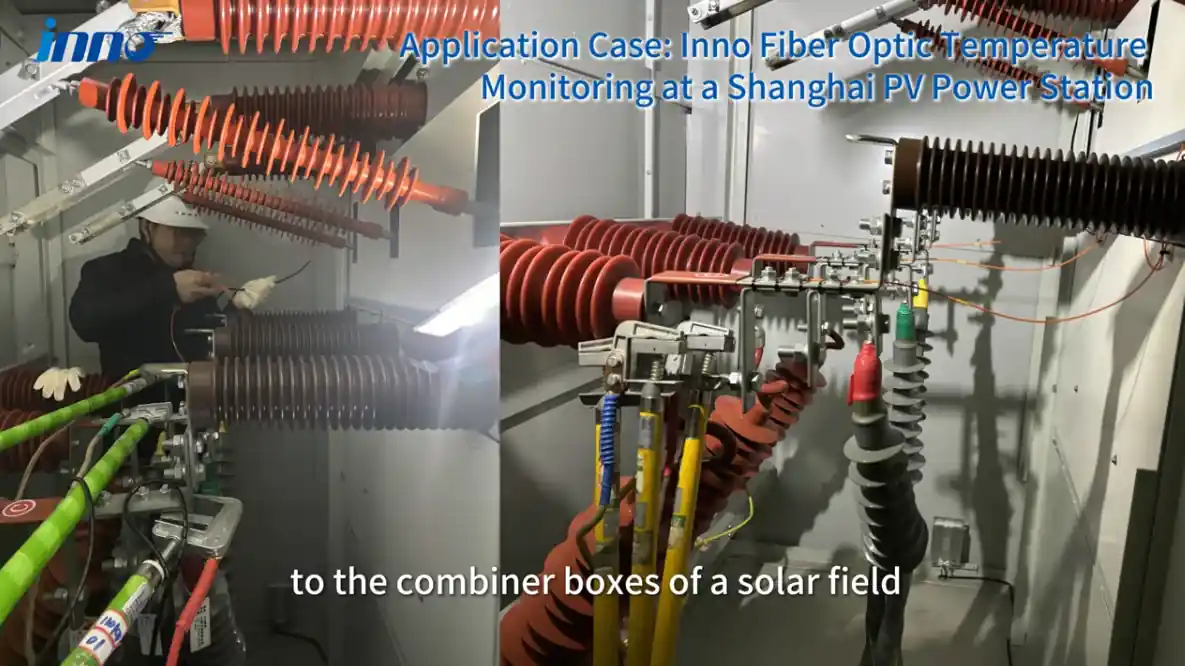
Relevant examples include switchgear temperature monitoring and motor and generator temperature monitoring.
RF and Microwave Equipment
Conductive probes and sensor leads can interact with RF or microwave fields depending on their position, geometry, and installation. Optical probes provide a non-conductive route for direct point measurement inside suitable RF or microwave processes.
Application details are available under industrial microwave temperature monitoring.
Strong Magnetic Fields
Research systems, test equipment, and MRI-related environments may restrict metallic sensing elements or conductive wiring near the measurement point. Optical probes provide another measurement approach where strong magnetic fields influence sensor selection.
Embedded Internal Measurement Points
Selected locations inside transformer windings, motor or generator windings, research equipment, and other assemblies may require direct temperature measurement from a point that becomes inaccessible after manufacture.
Fiber optic probes can be installed at predetermined locations when equipment construction or retrofit design provides access. Each probe reports the temperature at its installed position; it does not search for an unknown hottest point.
When Conventional Sensors May Be the Better Choice
Fiber optic sensing is not necessary for every industrial temperature measurement project. RTDs, PT100 sensors, thermocouples, thermistors, and infrared sensors remain suitable for a large proportion of industrial applications.
Common examples include:
- ordinary process piping
- accessible machinery surfaces
- low-voltage equipment
- conventional process control
- general HVAC and plant measurement
- applications without special electrical-isolation requirements
- locations without severe electromagnetic, RF, or magnetic-field constraints
Conventional sensors are often simpler to install, easier to replace, and already supported by existing plant instrumentation.
Fiber optic temperature sensors should therefore be selected because the measurement environment requires their electrical or optical characteristics, not simply because optical sensing is available.
More detailed comparisons are available in Fiber Optic Temperature Sensor vs PT100 and Fiber Optic Temperature Sensor vs Thermocouple.
Industrial Temperature Sensors by Application
Different temperature sensors for industrial applications are selected according to the measurement location, surrounding electrical environment, installation access, and required system integration.
| Application | Measurement Challenge | Common Sensor Options | When Fiber Optic May Be Considered |
|---|---|---|---|
| Transformer Windings | Internal measurement point under high electrical potential | Fiber optic probes; indirect oil or winding-temperature methods | Direct measurement at selected winding locations |
| Switchgear | Energized connections, compact space, strong current fields | Infrared, RTD, thermocouple and other point methods | Measurement points requiring electrical isolation or high EMI resistance |
| Motors & Generators | Internal winding points, strong electromagnetic fields and limited sensor-routing space | RTD, thermocouple, thermistor and selected optical sensors | Selected winding points where electrical isolation or high EMI resistance is required |
| Industrial Process Equipment | Different temperatures, process conditions and mounting requirements | RTD, thermocouple, infrared and specialized process sensors | Locations with electrical, RF or electromagnetic constraints |
| High-Voltage Testing | Test object operating at elevated electrical potential | Application-dependent measurement methods | Direct isolated measurement on selected test-object points |
| RF / Microwave Equipment | Possible interaction between conductive sensors and electromagnetic fields | Application-specific contact or non-contact methods | Non-conductive point measurement inside suitable RF or microwave environments |
| Laboratory / Test Systems | Variable setups, multiple points and changing test conditions | Thermocouple, RTD, thermistor, infrared and optical sensors | Electrical isolation, strong fields or embedded test points |
From Temperature Sensor to Monitoring System
Useful temperature monitoring depends on the complete measurement chain:
Measurement Point → Sensor / Probe → Cable / Optical Fiber → Monitoring Instrument → Alarm / Communication → PLC / SCADA
Sensor selection is only one part of this chain. Channel count, signal acquisition, alarm logic, communication interface, data logging, control-system integration, maintenance, and sensor replacement also influence the final design.
Fluorescence-based systems may include a fiber optic temperature probe, optical fiber or extension fiber, and a temperature transmitter, demodulator, or monitoring instrument. Single-channel and multi-channel configurations can be selected according to the number of measurement points.
System options are available under fiber optic temperature monitoring systems, while the overall measurement approach is described under fiber optic temperature measurement.
Information to Define Before Requesting a Temperature Monitoring System
Clear project information makes sensor and monitoring-system selection much more accurate. Useful RFQ information normally includes:
- equipment being monitored
- exact measurement points
- number of temperature points
- expected operating temperature range
- electrical voltage environment
- EMI, RF, or magnetic-field conditions
- available probe installation space
- required cable or optical-fiber routing
- distance between sensors and monitoring instrument
- required number of monitoring channels
- required communication interface
- PLC or SCADA integration requirements
- alarm or relay-output requirements
- whether the project is new equipment or a retrofit
Selecting the Right Sensor for the Measurement Environment
Industrial temperature sensor selection depends on where temperature must be measured and what conditions surround that point. Temperature range, electrical environment, installation access, response, accuracy, channel count, maintenance, and system integration should be evaluated together.
RTDs, thermocouples, thermistors, infrared sensors, and semiconductor sensors remain practical choices for many conventional industrial measurements. Fiber optic sensing serves a narrower but important group of applications where high voltage, EMI, RF, strong magnetic fields, embedded measurement points, or electrical isolation create limitations for conventional electrical sensors.
For projects involving these conditions, contact INNO engineering with the equipment type, measurement locations, number of points, temperature range, electrical environment, and required monitoring interface. A suitable fluorescence-based point sensing configuration can then be evaluated against the actual application requirements.