
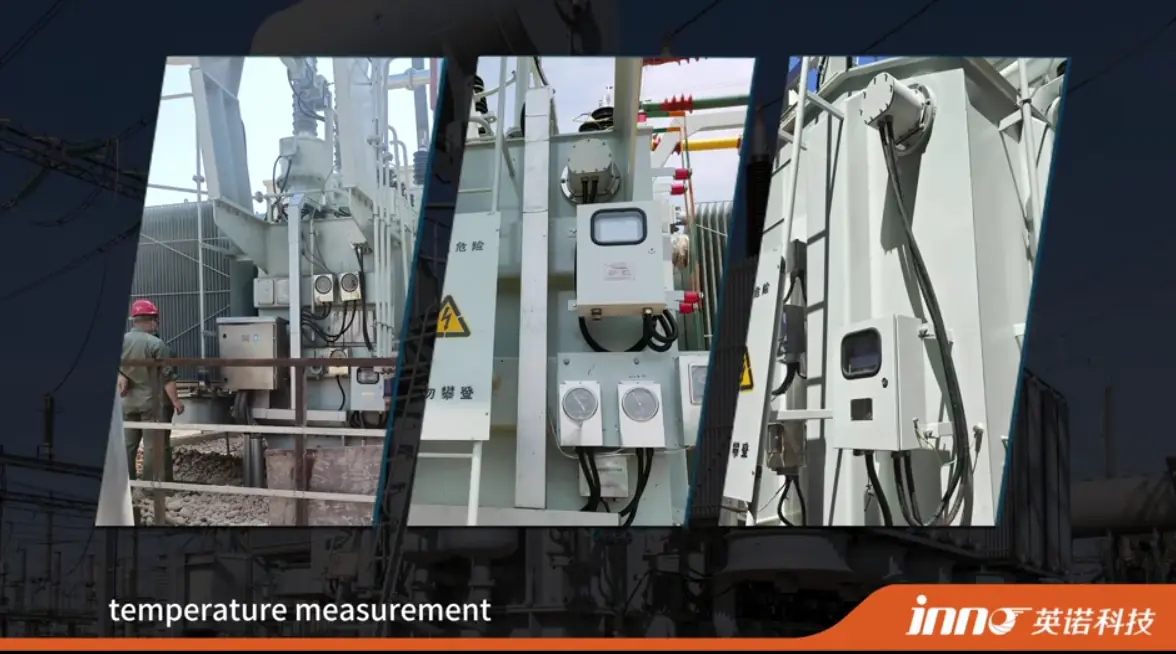
A winding temperature detector is used to determine the temperature of a winding in equipment such as transformers, motors and generators. The term is not tied to one fixed device. Depending on the equipment, it may refer to a winding temperature sensor such as an RTD, a transformer winding temperature indicator (WTI), or a fiber optic probe installed at a selected winding location.
Depending on the application, winding temperature may be measured directly at a physical point, or estimated indirectly from other thermal and electrical quantities. That difference is the main reason the term causes confusion, and it is the thread that runs through this article.
Key Takeaways
- "Winding temperature detector" is a broad engineering term, not the name of one fixed instrument.
- RTDs can directly measure temperature at the location where they are installed.
- A traditional transformer WTI often represents winding temperature through indirect thermal simulation rather than a sensor placed in the winding.
- Fiber optic probes directly measure selected physical winding locations, using an optical signal path.
- One point sensor measures one defined location. Several locations need several sensors.
- Transformer and motor winding monitoring do not necessarily use the same sensor arrangement.
- Selection depends on equipment type, electrical environment, measurement objective and installation access.
What Is a Winding Temperature Detector?
Windings generate heat because of electrical losses. The current flowing through the conductors produces resistive heating, and the heat has to be carried away by the cooling arrangement of the equipment. Temperature monitoring is used to observe the resulting thermal condition of the winding.
A winding temperature detector is the sensing or monitoring arrangement that provides this information. In practice it may be an embedded sensor, a temperature indication arrangement, a thermal simulation device or a direct optical probe. "Detector" does not necessarily mean the same hardware in every application, and a specification that asks for one should be read together with the equipment type and the measurement objective.
Winding Temperature Detector vs Sensor vs Indicator
The three terms are often used as if they were interchangeable. They describe different levels of the measurement chain.
Winding Temperature Detector
This is the broadest term. It refers to a sensing or monitoring arrangement used to detect, obtain or determine winding temperature. The arrangement may consist of a sensing element and an instrument, or of a device that calculates the value from other inputs.
Winding Temperature Sensor
A winding temperature sensor usually means the actual sensing element. Examples include an RTD, a thermistor, a thermocouple or a fiber optic probe. The sensor produces a signal that depends on temperature at its location.
Winding Temperature Indicator
A winding temperature indicator is normally an instrument that displays, simulates, calculates or processes a winding temperature value. In oil-immersed transformers, a WTI commonly uses top-oil temperature together with a load-related heating effect or thermal simulation to represent winding temperature. It is not correct to assume that a WTI sensor is always installed directly in the winding.
Some indicators also provide alarm or control outputs, so an indicator is not only a display. The specific outputs depend on the product and are outside the scope of this article.
Why Is Winding Temperature Monitored?
Winding temperature is influenced by electrical loading, losses, cooling performance, ambient conditions and local thermal conditions inside the equipment. Monitoring it gives information about how these factors combine during operation.
The information can be used to observe insulation thermal stress, detect overheating trends, check cooling performance and understand load behavior. A temperature reading is not a verdict on its own. Acceptable values and alarm settings depend on the equipment design, insulation system and applicable specification, so they should come from the equipment documentation and not from general figures.
RTD Winding Temperature Detectors
RTD stands for resistance temperature detector. Common designations such as PT100 and PT1000 refer to the nominal resistance of the element at a reference temperature. An RTD measures temperature through a predictable change of electrical resistance, which the connected instrument converts into a temperature value.
When an RTD is embedded or installed at a winding location, it measures the temperature near that location. RTD winding temperature sensors are common in motor stator windings and generator stator windings, and they are also used in dry-type electrical equipment and selected transformer arrangements. They are not used in every transformer winding, and it should not be assumed that a given transformer has one.
Advantages and Selection Considerations
RTDs offer several practical advantages:
- Direct measurement at the installed location
- A well-established industrial technology
- Suitability for continuous monitoring
- Easy integration with many conventional instruments
Selection considerations follow from the fact that the sensor is electrical. An RTD needs conductive wiring, so electrical isolation, lead routing, installation space and the electromagnetic environment all have to be considered. In high-voltage applications, electrical insulation and wiring requirements must be handled carefully. This does not rule out RTDs, and many high-voltage machines use them successfully.
Transformer Winding Temperature Indicator (WTI)
In traditional or common WTI arrangements for oil-immersed transformers, the sensor is generally not placed in the conductor winding. The device measures top-oil temperature and adds a load-dependent thermal simulation, often derived from the load current, to represent the winding temperature or winding hot-spot behavior.
Not every WTI is built the same way, and details differ between manufacturers and transformer designs. The general principle, however, is that the displayed value is a calculated or simulated representation based on measured inputs and model assumptions. This is a legitimate and widely used approach, and it is well suited to indication, alarm and cooling control functions on transformers that have no internal winding sensors.
Does a WTI Directly Measure Transformer Winding Temperature?
Not necessarily. Traditional transformer WTI arrangements generally provide an indirect or simulated winding temperature based on top-oil temperature and transformer load. The result is a useful thermal indication, but it is not a reading from a sensor at the winding conductor.
A full comparison of the two approaches is available in our article on transformer WTI vs fiber optic temperature sensor, so it is not repeated here.
Fiber Optic Winding Temperature Detectors
INNO's technology is fluorescence-based point fiber optic temperature sensing. A probe is installed with its sensing tip at a selected winding location, and the temperature is measured at that tip. An optical fiber carries the excitation and return optical signals between the sensing point and a compatible instrument, which converts the signal into a temperature value.
For oil-immersed transformers, a fiber optic winding temperature sensor allows direct temperature measurement at selected winding positions when the probe is built into the transformer during manufacturing.
Point Sensing Boundaries
The measurement principle sets clear limits that should be understood at the specification stage:
- One probe corresponds to one defined physical measurement point.
- Multiple probes give multiple independent winding temperature points.
- The fiber carries the signal but does not measure temperature along its length. This is point sensing, not distributed temperature sensing.
- One probe does not monitor the entire winding.
- The system does not automatically locate unknown hot spots. Where hot spots are of interest, probes are placed at selected or previously identified thermally critical winding locations.
Characteristics of Fiber Optic Probes
- Direct point measurement at the sensing tip
- Electrical isolation of the optical sensing path
- High resistance to electromagnetic interference
- Small sensing probe geometry
- Multi-point monitoring using several independent probes
These are characteristics of the sensing method. Whether a probe suits a particular winding depends on the design, the accessible measurement locations and the way the fiber can be routed out of the equipment.
RTD vs WTI vs Fiber Optic Winding Temperature Detection
The table compares the three approaches by how they work and where they are commonly used. It is a neutral comparison, and each entry reflects general characteristics that vary with the specific product and installation.
| Method | Measurement Principle | Direct or Indirect | Typical Application | Electrical Signal at Measurement Point | Main Selection Consideration |
|---|---|---|---|---|---|
| RTD | Electrical resistance changes with temperature | Direct, at the installed location | Motor and generator stator windings, dry-type equipment, selected transformer arrangements | Yes, conductive wiring runs to the sensing element | Wiring, insulation and routing in the electrical environment |
| Transformer WTI | Top-oil temperature plus a load-related thermal simulation | Indirect, calculated or simulated | Oil-immersed transformer indication, alarm and control arrangements | Not applicable, since no sensor is placed at the winding conductor in traditional arrangements | Whether calculated indication is sufficient or measured data at the winding is required |
| Fiber optic point sensor | Optical signal from the sensing tip, such as fluorescence behavior | Direct, at the sensing tip location | Transformer, motor and generator windings, including high-voltage or strong-field conditions | No, the signal path at the measurement point is optical | Probe placement, fiber routing and compatible instrument channels |
Direct vs Indirect Winding Temperature Detection
In direct measurement, a sensor physically measures temperature at a selected location. An RTD installed at a chosen point and a fiber optic probe installed at a chosen point are both examples. The reading describes that point.
In indirect determination, the winding temperature is derived from other quantities such as top-oil temperature, load current, a thermal model or a thermal simulation. A traditional transformer WTI is the standard example. The reading describes the calculated winding condition, based on the model.
Direct does not automatically mean more appropriate in every application. Indirect methods are simple, established and available without internal access to the winding, and direct methods provide measured data at chosen locations. They serve different engineering purposes, and the choice depends on what the project needs to know. Winding temperature can also be evaluated as an absolute value or as a temperature rise relative to an appropriate reference, as explained in our article on transformer temperature rise.
Winding Temperature Detectors in Transformers
In oil-immersed transformers, internal winding access after manufacturing is difficult. Direct internal probes therefore normally need to be planned during design and manufacturing. WTI arrangements and top-oil measurements are widely used as external monitoring arrangements, because they do not require access to the winding.
When fiber optic probes are built into the transformer, they can provide direct measurements at selected winding positions. Sustained winding and hot-spot temperature contributes to thermal stress on the insulation, a relationship covered in our article on transformer ageing.
For the range of measurement approaches available on transformers, see our page on transformer temperature monitoring. The individual methods, including how each one is applied, are compared in the article on how transformer winding temperature is measured.
Winding Temperature Detectors in Motors and Generators
Motors and generators commonly monitor stator winding temperature at selected embedded locations. Bearing temperature is monitored separately and serves a different purpose. The two should not be confused, since bearing temperature does not describe winding condition.
RTDs are widely used for stator winding monitoring in motors and generators. Fiber optic sensors may be considered where electrical isolation, a strong electromagnetic environment, high-voltage conditions or special test conditions make optical sensing useful. In that case, a motor winding fiber optic temperature probe is installed with its sensing tip at the selected winding location.
This section describes how winding temperature detection is implemented in motors and generators. It does not compare all motor sensor types in detail, since that is a separate question. For the broader application context, see motor and generator temperature monitoring.
Winding Temperature Indicator vs Winding Temperature Detector
Users searching for one term often mean the other. A detector is the broader term and can refer to the actual sensing or detection method, whether that is a sensor at a physical location or a calculation from other quantities. An indicator usually emphasizes display, indication, processing or simulation of a winding temperature value.
In transformers, WTI has a specific industry context, and it usually refers to the oil-and-load-based arrangement described above. Not every winding temperature indicator is only a display, since some include alarm or control functions. The specific outputs depend on the product and are not covered here.
Where Is a Winding Temperature Detector Installed?
Transformer Windings
Direct probes need selected physical locations inside the winding. These locations are agreed during design and manufacturing, when the winding is accessible. A probe reports the temperature at its own position and no other.
Motor and Generator Stator Windings
Embedded sensors can be positioned while the winding is being made. The positions depend on the machine design and the monitoring objective.
External or Indirect Arrangements
A WTI or top-oil arrangement may not involve any sensor embedded in the winding. The measurement is made in the oil, and the winding value is derived from it. Exact positions, layer numbers or distances are not fixed by any general rule and should come from the equipment design and engineering data.
Monitoring Multiple Winding Temperature Points
If several independent physical locations need to be monitored, several sensing points are needed. For fluorescence fiber optic point sensing, one point corresponds to one probe and one compatible active channel on the instrument.
As an example, three independent points would normally need three probes and at least three compatible active channels. This is only an illustration and not a universal design rule. The number of points depends on the equipment and the monitoring objective. Several probes provide several independent point measurements, and they do not form a distributed temperature profile.
How to Choose a Winding Temperature Detector
Working through the following points in order helps narrow the options:
- Equipment type: transformer, motor or generator.
- Measurement objective: what the temperature data will be used for.
- Direct measurement or indication: whether measured data at the winding is needed, or a calculated indication is enough.
- Expected temperature range: confirmed against the sensor or instrument documentation.
- Electrical voltage environment: the insulation and isolation demands at the measurement point.
- Electromagnetic environment: the effect of strong fields on wiring and signals.
- Number of measurement points: each independent location needs its own sensor.
- Installation access: whether the winding can be reached during manufacturing or maintenance.
- Available space: the room for the sensor at the intended point.
- Wiring or fiber routing: how the connection leaves the equipment.
- Required monitoring channels: enough compatible channels for all points.
- Integration requirements: the interface of the existing monitoring or control system.
- New equipment or retrofit: which of the two applies.
New Equipment vs Retrofit Installation
In a new transformer, motor or generator, embedded sensors can be planned during manufacturing. Measurement points can be agreed with the designer, sensors placed while the winding is accessible, and the routing of wires or fibers built into the construction.
In existing equipment, internal winding access may be restricted. It cannot be assumed that direct internal fiber optic sensors can always be retrofitted. Feasibility depends on physical access, the equipment design and the maintenance scope, and each case needs an engineering review.
Common Misunderstandings About Winding Temperature Detectors
"A WTI always measures the winding directly."
Not necessarily. Traditional transformer WTI arrangements commonly derive the winding value from top-oil temperature and load, so the result is calculated or simulated and not read from a sensor at the conductor.
"One detector measures the whole winding."
Point sensors measure only the locations where they are installed. Coverage of a winding requires enough sensors at suitable positions.
"Top-oil temperature is winding temperature."
They are different measurement quantities. Under load the winding is generally hotter than the oil around it, and the difference changes with loading and cooling.
"Multiple fiber optic probes are DTS."
They are not. Several probes still provide several independent point measurements, and no continuous profile along the fiber is produced.
"The same detector arrangement suits every transformer and motor."
Equipment design and measurement objective differ between applications, so the arrangement has to be chosen for each case.
Conclusion
A winding temperature detector is not one single sensor technology. Depending on the equipment, winding temperature may be measured directly using RTDs or fiber optic probes, or represented indirectly by devices such as a transformer WTI.
RTDs are an established form of direct electrical sensing at installed locations. A WTI is a transformer-oriented thermal indication and simulation approach. Fiber optic sensors provide direct point measurement through an optically isolated sensing path. None of the three is best in every case.
The appropriate method depends on the equipment, measurement point, electrical environment and whether the project requires direct temperature data or indirect thermal indication.
If your project requires direct winding temperature measurement, INNO can help review sensing locations, probe configuration, fiber routing and channel requirements.