
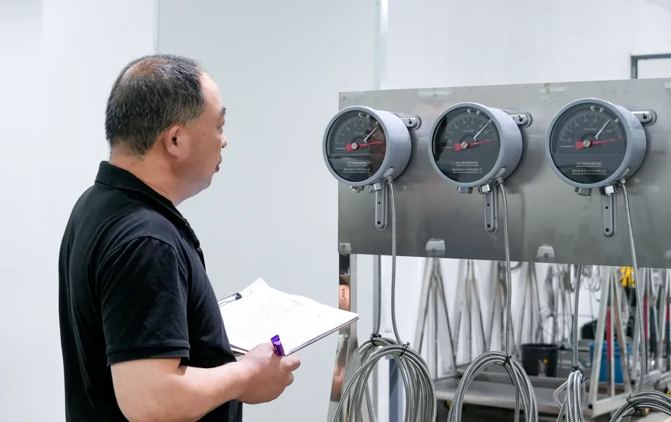
A transformer oil temperature gauge and a winding temperature gauge do not represent the same thermal condition. The oil temperature indicator (OTI) reflects oil temperature at its sensing location, while a conventional winding temperature indicator (WTI) commonly estimates winding thermal behavior using oil temperature and load-related compensation. Their display ranges, alarm settings and readings should therefore not be treated as interchangeable.
The distinction matters most when two dials on the same transformer show different numbers, or when someone asks which gauge has the "higher range." The answers depend on what each instrument represents, how it is built and how it was configured for a specific transformer.
Oil Temperature Gauge and Winding Temperature Gauge Are Not Measuring the Same Thing
Oil Temperature Indicator (OTI). The OTI shows the oil temperature obtained from its sensing arrangement. In many applications, the quantity of interest is the top-oil temperature, because oil at the top of the tank or near the oil outlet reflects the thermal state of the cooling circuit. The reading describes the oil at the sensing location, not the conductors.
Winding Temperature Indicator (WTI). The WTI represents the thermal condition of the winding. Depending on instrument design, that representation may be an estimate derived from oil temperature plus a load-related correction. It is a winding thermal indication, and it should not be assumed to be a conductor temperature read by a sensor embedded in the winding.
Both instruments belong to the broader field of transformer temperature monitoring, but they answer different questions. OTI and WTI are conventional indication approaches, and direct fiber optic measurement is a third approach with its own role.
Core Comparison: OTI vs WTI
| Item | Oil Temperature Gauge / OTI | Winding Temperature Gauge / WTI |
|---|---|---|
| Measured / represented quantity | Oil temperature at the sensing location, often top-oil | Winding thermal indication, often an estimated winding temperature |
| Measurement principle | Temperature sensing of the oil through a sensing bulb or equivalent element | In many conventional designs, oil temperature reference plus load-current-related thermal compensation (thermal image) |
| Relation to transformer load | Responds to load indirectly, through oil heating | Typically includes a load-dependent term, depending on instrument design |
| Relation to winding hot spot | Does not represent the hot spot directly | Intended to approximate winding thermal behavior; not a guaranteed hot-spot measurement |
| Typical sensor location | Oil pocket or thermowell, commonly near the top of the tank | Oil pocket or thermowell, with compensation derived from the load current |
| Display range | Instrument-specific; depends on gauge model and transformer specification | Instrument-specific; depends on gauge model and transformer specification |
| Alarm / trip use | Contacts configured per project and manufacturer requirements | Contacts configured per project and manufacturer requirements |
| Direct or indirect winding measurement | Not a winding measurement | Indirect in many conventional designs |
Oil Temperature Gauge vs Winding Temperature Gauge: 6 Main Differences
1. They Represent Different Temperatures
The OTI represents oil temperature. The WTI represents a winding thermal indication, which, depending on design, is an estimated winding temperature rather than a direct conductor measurement.
Because they represent different physical quantities, a difference between the two readings at the same moment is expected. A winding carries load losses and heats the surrounding oil, so the winding-related indication and the bulk oil reading are not required to match. A gap between them is a normal consequence of what each gauge represents, not a sign that one instrument is faulty.
2. Their Measurement Principles Are Different
An OTI senses the temperature of the oil where its sensing element is installed. The reading follows the oil and nothing else.
Many conventional WTI designs start from an oil temperature reference and add a correction related to the load current, often described as a thermal image or thermal compensation. The correction is intended to approximate how much the winding runs above the oil under the present load. The exact implementation varies by instrument design, so the principle should be read as a general concept rather than a description of every model.
The practical consequence is that the WTI output depends on both an oil measurement and a modeled or compensated term. For a fuller look at the indirect versus direct approaches, see how transformer winding temperature is measured.
3. Their Display Ranges Are Not Universal
There is no single universal oil temperature gauge range or winding temperature gauge range for every transformer.
The range printed on a dial or configured in a gauge depends on:
- instrument model
- transformer design
- expected operating temperature
- manufacturer specification
- alarm and protection philosophy
Two transformers can use gauges with different scales, and the OTI and WTI on the same transformer can also have different scales. A wider or narrower dial does not by itself say anything about the transformer's thermal capability.
Two points are easy to confuse:
- Scale range is not the normal operating range. The scale tells you what the instrument can display, not where the transformer is expected to run.
- Scale range is not the alarm setpoint. Alarm and trip contacts are set to values defined by the transformer specification and protection scheme, which can sit anywhere within the displayed scale.
The range section below separates these ideas in more detail.
4. WTI Responds to Load Differently
When load current increases, the winding generates more heat in the conductors. The winding thermal condition can rise differently from the bulk oil temperature, because the oil has to carry heat away through the cooling circuit and responds with its own thermal lag.
A WTI with load-related compensation reflects this load influence in its indication, while an OTI follows the oil and therefore responds to the same load change through a different path. For this reason, the two readings can move at different rates when load changes, and they can diverge during rising or falling load even if they agree reasonably well in steady conditions. The size of the effect depends on transformer design, cooling arrangement and instrument configuration, and no universal time constant applies.
5. OTI and WTI Serve Different Monitoring Functions
The OTI is oriented toward oil thermal condition. It supports observation of the cooling circuit and the general thermal state of the transformer oil.
The WTI is oriented toward winding thermal indication. It gives operators and protection systems a load-aware signal related to winding heating.
The two are complementary. One does not simply substitute for the other, and a project may use alarm or control logic from each for different purposes, such as cooling control from one signal and winding-related alarms from another. How those functions are allocated is a matter of the transformer specification and protection design.
6. Conventional WTI Is Different from Direct Fiber Optic Winding Measurement
A traditional WTI often provides an indirect or modeled winding indication. A fiber optic probe, when incorporated into the transformer design, can directly measure temperature at a selected winding location.
INNO uses fluorescence-based point fiber optic temperature sensing. In this approach, one probe is one defined physical sensing point, and multiple probes are multiple independent sensing points. A single probe measures only the location where it is installed, so covering several locations requires several independent probes and channels.
Fiber optic measurement therefore adds a different kind of data: a physical reading at a chosen point rather than an inferred value. It does not replace every OTI or WTI function by default, and it does not automatically find the hottest point. That topic is developed in the comparison section further down, and the full side-by-side treatment is in the existing article on winding temperature indicator vs fiber optic temperature sensor.
What Does "Range" Mean on a Transformer Temperature Gauge?
The word "range" is used for three separate ideas. Mixing them up is the most common source of confusion when people compare an oil temperature gauge with a winding temperature gauge.
Gauge Scale Range
This is the span of temperatures the instrument is able to display, from the lowest to the highest marking on the dial or the lowest to the highest value in the display. It is a property of the instrument model. It tells you the measurement capability of the gauge, not how the transformer behaves.
Expected Operating Range
This is the region of temperatures the equipment is expected to reach under actual working conditions, given its load, cooling and ambient environment. It comes from the transformer design and specification. It will not match the scale range, and it can differ between the oil and the winding.
Alarm and Trip Settings
These are the setpoints programmed into the gauge contacts or the monitoring system for protection and control. They are defined by the manufacturer, the project specification and the protection philosophy. They are not fixed by the dial scale, and they should always be verified against the transformer documentation rather than assumed from a typical value.
These three are not the same thing. A gauge with a wide scale does not imply a high operating temperature, and an alarm value is not the end of the scale. Generic numbers copied from one project should not be applied to another, because different manufacturers, designs and project configurations set these values differently.
Why Can OTI and WTI Show Different Temperatures?
Several factors can make the two readings differ without either reading being automatically wrong:
- Load. Higher load increases winding losses, which affects the winding indication and the oil at different rates.
- Oil thermal condition. The oil temperature depends on the cooling state, circulation and where the sensing point sits in the oil.
- Winding losses. Heat generated in the conductors reaches the sensing location only after it passes through insulation and oil.
- Thermal lag. The oil responds more slowly than the winding to changes in load, so the two can diverge during transients.
- Instrument design. Different gauges use different sensing and compensation arrangements.
- Sensor location. Where the sensing element sits changes what it reads.
- Thermal compensation method. The way a WTI applies its load-related correction determines how its indication relates to the oil temperature.
A difference between the readings is information about the transformer's thermal state, and it should be read in light of the factors above before any conclusion is drawn about instrument accuracy.
WTI vs Direct Fiber Optic Winding Temperature Measurement
| Method | What It Represents | Direct Physical Point Measurement | Typical Role |
|---|---|---|---|
| OTI | Oil temperature at the sensing location | No, it measures oil rather than a winding point | Oil thermal condition indication, alarm and control inputs |
| Conventional WTI | Winding thermal indication, often estimated from oil temperature and load compensation | Not in many conventional designs | Winding thermal indication, alarm and control inputs |
| Fiber optic winding probe | Direct temperature at the selected installed winding point | Yes, at that point | Direct winding measurement at chosen locations |
Direct point measurement does not mean automatic hot-spot location. Probe positions must be selected during transformer design or thermal planning.
For projects that need direct hot spot monitoring, the value of the fiber optic approach depends on where the probes are placed. An oil-immersed transformer winding fiber optic temperature sensor measures temperature at its installed point, so the quality of the information depends on the planning behind the placement. The practical side of choosing those points is covered in the article on where temperature sensors are placed in transformer windings.
When several winding locations are of interest, the system is configured with several independent probes and channels. An oil-immersed transformer fiber optic temperature monitoring system is arranged around the number of points, the fiber routing and the monitoring channels the project requires.
How Should Engineers Interpret OTI and WTI Readings Together?
A few working habits keep the interpretation grounded:
- Compare each reading with its own instrument specification. The OTI and WTI have different scales, sensing arrangements and settings, so each reading belongs against its own reference.
- Look at trends rather than one isolated value. A rising or falling trend over time says more than a single snapshot, especially during load changes.
- Relate readings to transformer load. The WTI in particular carries a load-related term, so the load at the time of reading is part of the context.
- Verify alarm settings against transformer and manufacturer requirements. Setpoints should come from the documentation for that unit, not from a typical value used elsewhere.
- Investigate unexpected divergence. If the gap between OTI and WTI changes in a way that load, cooling state and thermal lag do not explain, check the cooling system, the sensing installation and the instrument configuration.
- Do not infer exact winding hot-spot temperature from OTI alone. The OTI reflects oil, and the winding hot spot depends on the winding design and on where heat is generated. The article on what causes hot spots in transformers explains why a hot spot is not the same as any single gauge reading.
Example: Oil Temperature Rises More Slowly Than Winding Indication
Consider a transformer in which load increases. The WTI indication rises, because its load-related compensation responds to the higher current. The bulk and top-oil temperature follow the load change differently, since the oil heats up through the cooling circuit and with its own thermal lag, so the OTI moves at a different pace.
If the transformer also has a direct fiber optic probe at a selected winding location, that probe provides a third, separate measurement: the physical temperature at that installed point. It is neither the oil temperature nor the modeled winding indication.
The three readings describe three different things: oil temperature, a winding thermal indication and the temperature at one defined winding point. They are not expected to agree, and the differences carry information about how heat moves from the winding into the oil.