
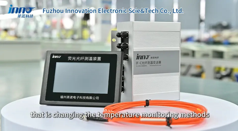
Fiber optic temperature measurement uses an optical probe connected by optical fiber to a monitoring instrument to obtain a temperature value at a specific physical location. A fiber optic temperature sensor does not carry an electrical measurement signal at the sensing point, which is why the method is often selected for high-voltage, strong EMI, magnetic-field, RF and microwave environments. This guide explains how the measurement chain works, what a probe actually measures, and where the method is typically applied.
- Fiber optic temperature measurement uses an optical probe and optical fiber to measure temperature at a selected physical point.
- The sensing path carries optical signals rather than an electrical measurement signal at the probe location.
- A point fiber optic temperature sensor measures only the location where the probe is installed.
- Multiple probes are required when several independent temperature points must be monitored.
- The method is especially useful in high-voltage, strong EMI, magnetic-field, RF and microwave environments where electrical isolation is important.
- Temperature data is converted by a monitoring instrument and can then be sent to PLC, SCADA, DAQ or other platforms where supported.
Fiber Optic Temperature Measurement Guide
- What Is Fiber Optic Temperature Measurement?
- How Fiber Optic Temperature Measurement Works
- What Does a Fiber Optic Temperature Sensor Measure?
- Fiber Optic Temperature Measurement System Components
- Fiber Optic vs Conventional Temperature Measurement
- Where Is Fiber Optic Temperature Measurement Used?
- High-Voltage and EMI Temperature Measurement
- Multi-Point Fiber Optic Temperature Measurement
- Fiber Optic Temperature Monitoring and System Integration
- When Should You Choose Fiber Optic Temperature Measurement?
- Fiber Optic Temperature Measurement System Selection Checklist
- INNO Fiber Optic Temperature Measurement
- Fiber Optic Temperature Measurement FAQ
What Is Fiber Optic Temperature Measurement?
Fiber optic temperature measurement is a method of measuring temperature using an optical temperature probe connected by optical fiber to a temperature monitoring instrument. This article focuses on point fiber optic temperature measurement rather than distributed fiber sensing.
Three components work together in this type of optical temperature measurement:
- Sensor / Probe - the temperature-sensitive sensing point, installed at the physical location being measured.
- Optical Fiber - carries the optical excitation and return signal between the probe and the instrument.
- Monitoring Instrument - interrogates the probe and converts the optical response into a temperature value.
This arrangement provides point temperature measurement without an electrical measurement signal path at the sensing tip itself.
How Does Fiber Optic Temperature Measurement Work?
The measurement chain can be summarized as: Fiber Optic Probe → Optical Fiber → Monitoring Instrument → Temperature Data → PLC / SCADA / DAQ if required.
- The instrument sends an optical signal through the fiber.
- The temperature-sensitive probe responds according to its temperature.
- The optical response returns to the monitoring instrument.
- The instrument converts that response into a temperature value.
INNO probes use fluorescence-based point fiber optic temperature sensing to generate this optical response. For a more detailed explanation of the sensing principle, see Fluorescent Fiber Optic Temperature Sensing Technology.
What Does a Fiber Optic Temperature Sensor Actually Measure?
A point fiber optic temperature sensor measures the temperature at the physical location of the sensing tip. It does not measure the temperature of a whole transformer, a whole busbar, a whole motor, or a whole microwave chamber, and it does not automatically locate the hottest point in a system. If more than one location needs to be measured, more than one probe is required.
| Measurement Setup | What the Reading Represents |
|---|---|
| One probe | Temperature at one installed sensing point |
| Three probes | Three independent physical temperature points |
| Six probes | Six independent temperature points |
| Multi-channel system | Several independent probes read by one compatible monitoring instrument |
The number of probes and channels follows the number of independent measurement points that need to be monitored, not the overall size of the equipment.
What Is Included in a Fiber Optic Temperature Measurement System?
A typical fiber optic temperature measurement system, or fiber optic temperature monitoring system, generally includes the following elements:
- Fiber optic temperature probe
- Optical fiber / extension assembly
- Monitoring instrument / transmitter / demodulator
- Power supply as required
- Local display where supported
- Communication output where supported
- PLC / SCADA / DAQ connection where required
The probe and the monitoring instrument perform different functions. The probe produces the temperature-dependent optical response, while the monitoring instrument converts that response into usable temperature data and, where supported, communication outputs. See What Is a Fiber Optic Temperature Sensor and How Does It Work? for more detail on the probe itself.
Fiber Optic Temperature Measurement vs Conventional Temperature Measurement
| Method | Measurement Type | Signal Path | Main Strength | Main Limitation / Consideration |
|---|---|---|---|---|
| Fiber Optic | Direct installed-point measurement | Optical | Electrical isolation and high EMI immunity along optical path | Requires compatible optical monitoring instrument |
| PT100 / RTD | Direct installed-point measurement | Electrical resistance | Widely used and easy to integrate in conventional systems | Electrical wiring and isolation must be considered |
| Thermocouple | Direct installed-point measurement | Thermoelectric voltage | Broad industrial use and suitable for many temperature ranges | Signal wiring and electrical environment must be considered |
| Infrared | Surface temperature measurement | Non-contact optical | No contact with target | Requires optical access / line of sight and measures accessible surfaces |
Each method has situations where it is practical. See Fiber Optic Temperature Sensor vs PT100: Key Differences for a closer comparison of these two direct-contact methods.
Where Is Fiber Optic Temperature Measurement Used?
| Application | What Is Measured | Why Fiber Optic Measurement Is Relevant |
|---|---|---|
| Transformer | Selected winding / hot-spot candidate locations | Direct point measurement inside high-voltage winding environment |
| Switchgear | Busbars, joints, cable terminations | Electrical isolation and multi-point monitoring |
| Motors | Selected stator winding locations | Direct winding measurement with high EMI immunity along the optical sensing path |
| High-Voltage Testing | Devices, components or test objects | Electrical isolation during high-voltage measurement |
| MRI / Strong Magnetic Fields | Selected equipment or test points | Electrically isolated optical sensing path at the probe location |
| Industrial Microwave / RF | Material, chamber or equipment points | Suitable where conductive sensor wiring may interfere with measurement environment |
| Power Electronics | IGBT / SiC / selected module locations | Compact direct point measurement for test and development |
Not every application requires fiber optic measurement, but it is especially useful where electrical isolation matters. For motor winding measurement specifically, see How Is Motor Winding Temperature Measured?, and for busbar and joint monitoring see How to Monitor Temperature in Switchgear Busbars, Joints and Cable Terminations.
Why Is Fiber Optic Temperature Measurement Used in High-Voltage and EMI Environments?
Several characteristics make fiber optic temperature measurement relevant for high-voltage temperature measurement and temperature measurement in strong electromagnetic fields:
- Optical sensing path is electrically isolated.
- The optical fiber carries the measurement optically rather than as an electrical sensor signal at the sensing point.
- High EMI immunity along the optical sensing path.
- Probe can be positioned near selected energized or electrically sensitive locations when equipment design allows.
- Monitoring instrument can remain away from the sensing point.
The monitoring instrument and external communication wiring remain electronic components, so overall system design and clearance still need to follow the applicable equipment and safety requirements. More detail on this topic is available in Why Use Fiber Optic Temperature Sensors for High-Voltage Temperature Measurement?
How Does Multi-Point Fiber Optic Temperature Measurement Work?
One point probe normally corresponds to one active measurement channel. For example, three probes provide three independent points, six probes provide six independent points, and twelve probes provide twelve independent points, depending on the monitoring instrument used.
Typical fiber optic temperature monitoring system configurations may include 1-4 channels for compact or OEM configurations where applicable, 3 / 6 / 9 / 12 / 16 channels for equipment monitoring applications depending on the instrument, and special configurations that may reach approximately 64 channels depending on the system architecture. Not every model supports every channel count. For guidance on selecting a channel count, see How Many Channels Do You Need for Fiber Optic Temperature Monitoring?
How Does Fiber Optic Temperature Monitoring Connect to PLC, SCADA or DAQ?
A fiber optic probe does not normally communicate directly with PLC or SCADA. The link generally follows this path: Fiber Optic Probe → Monitoring Instrument → Industrial Interface → PLC / SCADA / DAQ.
Depending on the monitoring instrument, common interfaces include:
- RS485 with a supported protocol such as Modbus RTU
- 4-20 mA analog output
- Alarm relay
- CAN where supported
- Ethernet / TCP/IP where supported
Not every instrument model includes every interface. For a closer look at connecting a fiber optic temperature monitoring system to third-party platforms, see How Can Fiber Optic Temperature Monitoring Systems Connect to PLC, SCADA and Third-Party Platforms?
When Should You Choose Fiber Optic Temperature Measurement?
| Measurement Requirement | When Fiber Optic Measurement Fits |
|---|---|
| High-voltage sensing point | Especially relevant where electrical isolation is required |
| Strong EMI environment | Especially relevant because the optical sensing path has high EMI immunity |
| Strong magnetic field | Relevant where electrically isolated optical sensing is needed |
| Direct internal point measurement | Relevant where a point probe can be installed at the required location |
| Multiple independent points | Suitable with multi-channel monitoring instrument |
| Conventional low-voltage process measurement | PT100 / thermocouple may also be practical |
| Accessible surface only | Infrared may be practical |
| Existing equipment with no internal access | Selection depends on available mounting and measurement location |
What Should Be Defined Before Selecting a Fiber Optic Temperature Measurement System?
- What equipment is being measured?
- What exact physical points require temperature measurement?
- How many independent points are required?
- What temperature range is expected?
- What probe diameter or installation space is available?
- What fiber length is required?
- Where will the monitoring instrument be installed?
- Is local display required?
- Is PLC / SCADA / DAQ integration required?
- Which communication interface is required?
- Is the project a standard configuration or OEM / ODM integration?
For temperature range and fiber length specifically, see What Temperature Range Can a Fiber Optic Temperature Sensor Measure? and How to Choose the Right Fiber Length for a Fiber Optic Temperature Sensor. For a broader selection walkthrough, see How to Choose a Fiber Optic Temperature Sensor.
INNO Fiber Optic Temperature Measurement Systems
INNO provides fluorescence-based point fiber optic temperature probes, monitoring instruments and configurable multi-channel measurement systems for electrical, industrial, medical and test applications.
- Direct point temperature measurement
- Electrically isolated optical sensing path
- High EMI immunity along the optical sensing path
- Compact probe options
- Custom fiber length
- Multi-channel measurement
- Monitoring instruments for different channel requirements
- PLC / SCADA / DAQ integration through compatible interfaces
- OEM / ODM options for equipment manufacturers and system integrators
Typical INNO point-probe references may include a temperature range of approximately -40 to 260 C, accuracy of approximately +/-0.5 to +/-1 C, response under 1 s, probe diameter of approximately 2-3 mm, and fiber length of approximately 0-20 m. Channel configurations depend on the monitoring instrument and project requirements, and exact specifications depend on probe, instrument and project configuration.