
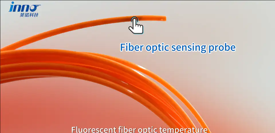
A fiber optic temperature sensor is a temperature measurement device that uses an optical fiber and an optical sensing element to measure temperature at a selected physical point. This guide covers fluorescence-based point fiber optic temperature sensing. In this design, the probe tip contains a temperature-sensitive fluorescent material. Optical energy travels through the fiber to the probe, the sensing material produces a temperature-dependent optical response, and a monitoring instrument converts that response into a temperature reading.
Unlike PT100 sensors or thermocouples, the sensing path does not rely on an electrical temperature-measurement signal at the probe. That makes fiber optic temperature measurement a practical choice for high-voltage equipment, strong electromagnetic fields, RF / microwave environments and other applications that need an electrically isolated measurement. Conventional sensors still fit many industrial jobs. This guide explains where the optical approach fits and how the measurement chain is built.
Key Takeaways
- A fiber optic temperature sensor measures temperature using optical signals rather than an electrical sensing signal at the probe.
- One point probe measures one defined physical temperature location.
- The probe, optical fiber and monitoring instrument work together as one measurement chain.
- The monitoring instrument converts the optical response into temperature data.
- The optical sensing path provides electrical isolation and EMI immunity.
- Fiber optic temperature sensors are used in transformers, high-voltage equipment, RF / microwave systems, motors, generators and test equipment.
What Is a Fiber Optic Temperature Sensor?
A fiber optic temperature sensor measures the temperature of a chosen point by sending light to a sensing element and reading the optical response that comes back. The measured value is a temperature at that point, not an average over a surface or a volume.
A typical point fiber optic temperature sensor system includes:
- Sensing probe
- Optical fiber
- Optional extension fiber
- Temperature transmitter / demodulator
- Monitoring instrument
The word "sensor" is used in two ways on the market. Some suppliers use it for the probe only. Others use it for the whole probe-plus-instrument system. When you compare quotations, confirm which one is meant. The probe is the element installed at the measurement point, while the monitoring instrument performs optical signal processing and converts the response into temperature data.
What Is Inside the Fiber Optic Temperature Probe?
The probe has three functional parts:
- Probe tip: contains the temperature-sensitive fluorescent sensing material. This is the sensing point.
- Optical fiber: sends light from the instrument to the tip and returns the optical response.
- Housing or protective structure: provides mechanical protection, positioning and thermal contact with the target.
Probe diameter is typically around 2-3 mm, and the structure can be adapted to the equipment and the measurement point. The exact sensing material and formulation are manufacturer-specific; buyers normally need the probe's verified operating range and application compatibility rather than the proprietary material formulation.
How Does a Fiber Optic Temperature Sensor Work?
The measurement follows six steps:
- The monitoring instrument sends light through the optical fiber.
- The light reaches the temperature-sensitive fluorescent material at the probe tip.
- The sensing material produces an optical response that changes with temperature.
- The optical response travels back through the fiber.
- The monitoring instrument analyzes the optical response.
- The instrument converts the result into a temperature value.
Temperature is determined from characteristics of the fluorescent response rather than from electrical resistance or thermoelectric voltage. In fluorescence-based systems, temperature can be determined from the temperature-dependent decay behavior of the fluorescent response. The sensing probe does not require active electronics at the measurement point and does not produce an electrical temperature-measurement signal there.
For the underlying sensing platform in more depth, see the fluorescent fiber optic temperature sensing technology page.
Is the Optical Fiber Itself the Temperature Sensor?
Not exactly. In this point sensor, the defined sensing point is located at the probe tip, where the sensing element sits. The fiber mainly carries optical signals between the probe and the monitoring instrument.
This differs from sensing technologies where the fiber acts as a continuous measurement medium along its length. Here, the fiber is the signal path. Bending, routing and extending it changes where the instrument sits, not where the temperature is measured.
What Is Point Fiber Optic Temperature Measurement?
Point measurement means one probe equals one defined physical sensing point. Three probes give three independent measurement points, which normally use three active measurement channels.
A probe does not measure the whole transformer, cabinet or chamber. It reports the temperature at the probe tip location. To monitor several locations, you need multiple probes connected to a multi-channel monitoring instrument. Where you place each probe therefore decides how useful the reading is.
What Is the Difference Between the Probe and the Monitoring Instrument?
| Component | Main Function | Typical Location |
|---|---|---|
| Fiber Optic Temperature Probe | Measures temperature at a selected physical point | Inside or near the equipment |
| Optical Fiber | Carries the optical signal | Between probe and instrument |
| Temperature Transmitter / Demodulator | Processes the optical response and converts it to temperature data | Control cabinet or monitoring location |
| Multi-Channel Monitoring Instrument | Processes multiple probe channels and may provide display and communication | Control room, panel or equipment cabinet |
The probe does not normally provide RS485 or Modbus directly. Communication normally occurs at the monitoring instrument or transmitter.
Why Does Fiber Optic Temperature Sensing Provide Electrical Isolation?
The optical measurement path does not use conductive electrical measurement wiring at the sensing point. Electrical potential at the sensing point is therefore not carried back to the instrument through an electrical sensor lead. The optical measurement path is non-conductive.
This suits high-voltage equipment, energized structures and locations with strong electric fields. Fiber optic sensing helps provide an electrically isolated temperature measurement path. It does not remove the need for proper insulation design, clearances and installation practice.
Why Are Fiber Optic Temperature Sensors Immune to EMI?
Optical signals are not affected by electromagnetic interference in the same way as conductive electrical measurement wiring. Fiber optic sensing is therefore well suited to measurements near high-voltage equipment, motors and generators, RF and microwave sources, power electronics and other strong electromagnetic environments.
The limit is worth stating. Immunity applies along the optical sensing path. The monitoring instrument and its communication wiring are still electronic components and need normal engineering installation, such as proper grounding, shielding and cable routing.
Fiber Optic Temperature Sensor vs PT100 vs Thermocouple
PT100 / RTD sensors and thermocouples remain widely used in conventional industrial temperature measurement. Fiber optic sensors are especially useful when electrical isolation, EMI immunity, non-conductive sensing or direct point measurement in electrically difficult environments is required.
| Sensor Type | Measurement Signal | Conductive Leads at Sensing Point | EMI Consideration | Typical Use |
|---|---|---|---|---|
| Fiber Optic | Optical | No conductive measurement signal | High immunity along the optical path | High-voltage, EMI and isolated measurement |
| PT100 / RTD | Electrical resistance | Yes | Installation-dependent | Conventional industrial temperature measurement |
| Thermocouple | Electrical voltage | Yes | Installation-dependent | Wide-range industrial temperature measurement |
What Temperature Range Can a Fiber Optic Temperature Sensor Measure?
A typical reference range for INNO point probes is approximately -40 to 260 °C, depending on probe configuration. Different probe structures can be selected for different temperature ranges and applications, so confirm the range against the exact probe model and its operating environment.
How Accurate Are Fiber Optic Temperature Sensors?
Typical INNO accuracy is approximately ±0.5 to ±1 °C, depending on probe and instrument configuration.
Sensor accuracy and installed measurement uncertainty are not the same thing. The result you get in the equipment also depends on probe placement, thermal contact, installation quality, target material and system configuration. A well-specified probe that is poorly mounted will not give a representative reading.
How Fast Does a Fiber Optic Temperature Sensor Respond?
A typical INNO point-probe response reference is under 1 s, depending on probe structure and measurement conditions. In practice, the response you see also depends on:
- Sensing-tip design
- Thermal contact with the target
- Adhesive, tape or mounting method
- Target material
- Airflow
- Thermal mass of the measured object
How Long Can the Optical Fiber Be?
Typical INNO configurations offer approximately 0-20 m of fiber, depending on probe structure and project requirements. For many equipment types, 3-5 m is a practical starting reference.
The final length depends on internal routing, feedthrough, equipment exit, external routing, the monitoring instrument location and an installation allowance. Measure the real route rather than the straight-line distance, and avoid ordering more fiber than the route needs.
Can Multiple Fiber Optic Temperature Sensors Be Monitored Together?
Yes. One point probe normally corresponds to one active measurement channel, and a multi-channel instrument can read several independent temperature points. Common configuration patterns include:
- Switchgear / box-type substations: 3 / 6 / 9 / 12 channels
- Dry-type transformers: 3 / 4 / 6 / 7 channels
- Oil-immersed transformers: 6 / 8 / 9 / 12 / 16 channels
- Special test, power electronics and laboratory systems: approximately 1-64 channels, depending on instrument and project requirements
These are common configuration patterns, not mandatory industry standards.
Where Are Fiber Optic Temperature Sensors Used?
| Application | Typical Measurement Point | Why Fiber Optic Sensing Is Used |
|---|---|---|
| Oil-Immersed Transformer | Winding / selected hot spot | Direct internal measurement and electrical isolation |
| Dry-Type Transformer | Winding / selected coil position | Direct point measurement |
| Switchgear | Busbar / joint / cable termination | Electrical isolation near energized equipment |
| Motor and Generator | Winding / stator | Strong electromagnetic field |
| RF / Microwave Equipment | Internal material or selected process point | Non-conductive sensing path |
| High-Voltage Testing | Test object | Remote, electrically isolated measurement |
| Power Electronics | Module / selected device location | Switching and EMI environment |
| Laboratory Equipment | Selected test point | Flexible point measurement |
These are typical application examples, not mandatory sensor configurations.
How Are Fiber Optic Temperature Sensors Used in Transformers?
In oil-immersed transformers, fiber optic probes may be embedded at selected winding locations during manufacturing. In dry-type transformers, probes may be positioned at selected winding or structural locations, depending on the design.
The probe measures the selected point. It does not automatically locate the hottest point, so probe positions should follow the transformer design and thermal analysis. Winding measurement methods are covered in more detail in a dedicated transformer guide.
How Are Fiber Optic Temperature Sensors Used in RF and Microwave Equipment?
Fiber optic probes can measure temperature inside or near RF / microwave environments without conductive electrical measurement leads at the sensing point. This suits microwave heating, dielectric heating, RF test systems and material testing, where metallic sensor leads can disturb the field or pick up interference.
How Is a Fiber Optic Temperature Probe Installed?
Common mounting approaches include a cable tie, high-temperature tape, thermally conductive adhesive, a mechanical connector or a clamp. The right method depends on the equipment and the sensing point.
Whatever the method, the installation should:
- Keep the probe stable
- Maintain representative thermal contact
- Avoid crushing the probe or fiber
- Avoid unnecessary tension
- Route the fiber correctly
Can Fiber Optic Temperature Monitoring Connect to PLC or SCADA?
Yes, through the monitoring instrument or transmitter, where compatible interfaces are provided. Possible integration options include RS485, Modbus RTU where supported, 4-20 mA, alarm relay, CAN and Ethernet / TCP/IP. Available interfaces depend on the instrument model and configuration.
The probe itself does not normally communicate directly with a PLC or SCADA system.
What Does a Complete Fiber Optic Temperature Monitoring System Include?
Depending on the project, a fiber optic temperature monitoring system may include:
- Fiber optic temperature probe
- Optical fiber
- Fiber extension or extension cable where required
- Temperature transmitter / demodulator
- Multi-channel monitoring instrument where required
- Power supply
- Communication interface
- Alarm output where supported
- PLC / SCADA integration where required
Not every project needs every item. The exact scope depends on the equipment, the number of points and the monitoring requirements.
How to Choose a Fiber Optic Temperature Sensor
Work through these points in order:
- Define the measurement point.
- Confirm the temperature range.
- Confirm probe diameter and structure.
- Determine fiber length.
- Determine the number of sensing points.
- Select the channel quantity.
- Confirm the electrical and EMI environment.
- Select the monitoring instrument.
- Confirm the communication interface.
- Confirm the mounting method.
Fiber Optic Temperature Sensor Selection Guide
| Selection Item | What to Confirm |
|---|---|
| Measurement Point | Exact physical location to be measured |
| Temperature Range | Expected minimum and maximum operating temperature |
| Probe Structure | Diameter, shape and mechanical requirements |
| Fiber Length | Actual routing distance |
| Number of Points | How many independent locations require measurement |
| Channel Count | Normally one active channel per point probe |
| Electrical Environment | High voltage, EMI, RF or ordinary industrial environment |
| Monitoring Instrument | Display, channel count and signal processing requirements |
| Communication | RS485 with a supported protocol, 4-20 mA, relay, CAN, Ethernet / TCP/IP or other supported interface |
| Mounting | Cable tie, tape, adhesive, connector, clamp or application-specific structure |
Common Fiber Optic Temperature Sensor Misunderstandings
1. The entire optical fiber measures temperature.
In this point sensing system, the defined sensing location is at the probe tip. The fiber carries the optical signal.
2. One probe measures the entire equipment.
One point probe measures one selected physical location. Several locations need several probes.
3. Fiber optic sensors are always more accurate than PT100 or thermocouples.
Accuracy depends on sensor technology and configuration. Electrical isolation and EMI immunity are often the main advantages.
4. The fiber optic probe connects directly to a PLC.
Normally the probe connects to a monitoring instrument or transmitter first. The instrument provides the PLC or SCADA interface.
5. Longer fiber always improves the system.
Fiber length should follow the actual routing requirements. Extra length adds handling and storage work without improving the measurement.
6. Every fiber optic temperature sensor uses the same technology.
Different fiber optic sensing technologies exist. This article focuses specifically on fluorescence-based point sensing.