
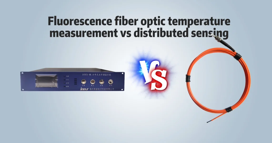
Fluorescence fiber optic temperature sensing and distributed temperature sensing (DTS) are both forms of fiber optic temperature sensing, but they are built on different measurement architectures. Fluorescence sensing is typically a point measurement technology, while DTS is a distributed measurement technology that reports temperature along the length of an optical fiber.
The choice between them depends on the nature of the measurement problem: does the application require the temperature at one or more specific, predefined physical locations, or does it require temperature information at many positions along an extended fiber route? This question, more than any single performance specification, determines which architecture fits.
What Is Fluorescence Fiber Optic Temperature Sensing?
Fluorescence fiber optic temperature sensing uses a fluorescent material located at the tip of a probe. An excitation light source is sent through the fiber to this material, causing it to fluoresce. The fluorescence decay behavior of the material changes with temperature, and a monitoring instrument evaluates this decay response to calculate the temperature at the probe tip.
Each probe corresponds to one defined physical measurement point. These fiber optic temperature sensors use the optical fiber primarily as a signal path between the sensing tip and the monitoring instrument, rather than as the sensing medium itself.
What Is Distributed Temperature Sensing (DTS)?
Distributed temperature sensing (DTS) uses the optical fiber itself as the sensing medium along its entire length. Rather than relying on a discrete sensing element at one point, a DTS system analyzes light scattered back from within the fiber as it travels along the fiber's length, commonly using Raman-based scattering methods.
This allows a DTS system to provide position-related temperature information at many points along the fiber, effectively producing a temperature profile along the route the fiber follows. DTS is one form of distributed fiber optic sensing; other distributed fiber optic sensing methods exist for parameters such as strain or acoustic signals, but this article focuses specifically on distributed temperature sensing.
Fluorescence Point Sensing vs DTS: Key Differences
| Aspect | Fluorescence Point Sensing | Distributed Temperature Sensing (DTS) |
|---|---|---|
| Measurement architecture | Discrete sensing element at the probe tip | Optical fiber itself acts as the distributed sensing medium |
| Sensing location | Defined physical point at the tip of each probe | Position-resolved temperature measurement along the installed sensing fiber |
| Spatial coverage | Limited to the installed probe locations | Extends along the full length of the installed fiber |
| Number of measurement points | One point per probe; multiple probes give multiple independent points | Many position-related readings generated along a single sensing fiber |
| Sensor / fiber role | Fiber carries the optical signal to and from a separate sensing element | Fiber is the sensing element and the signal path at the same time |
| Measurement resolution concept | Not applicable in the spatial sense; each probe is a single point | Spatial resolution along the fiber, determined by the specific DTS system design |
| Typical installation length | Fiber route connects each defined sensing point to the monitoring instrument | Designed for distributed measurement over an extended sensing-fiber route |
| Response considerations | Influenced by probe design, thermal mass, and mounting | Influenced by fiber length, acquisition settings, and system design |
| Accuracy considerations | Depends on the specific probe and instrument design | Depends on the specific system design, fiber length, and acquisition parameters |
| Temperature range considerations | Determined by the fluorescent material and probe design used | Determined by the fiber, cabling, and system design used |
| Instrument architecture | Interrogation unit reads fluorescence decay signals from discrete probes | Interrogation unit analyzes scattered light returned along the fiber |
| High-voltage / EMI environment | Suitable, since the sensing signal path is optical | Suitable, since the sensing signal path is optical |
| Installation complexity | Individual probes installed at specific measurement points | Continuous fiber run installed along the monitored route |
| Best-fit applications | Known, predefined measurement locations | Long linear assets where location-related temperature matters |
| System integration | Multiple probes connect to a multi-channel point-sensing instrument | Sensing fiber is connected to a DTS interrogation unit |
Point Measurement vs Distributed Measurement
With fluorescence sensing, one probe measures one defined point. If a project requires temperature data from several locations, several probes are installed and connected to a monitoring instrument capable of reading multiple channels. Each of those readings still corresponds to an independent, predefined physical location.
With DTS, a single fiber generates a series of position-related temperature measurements along the sensing fiber. The measurement is not tied to a small number of predefined points; instead, it covers the route the fiber physically follows.
This distinction is the core difference between the two technologies: fluorescence sensing answers "what is the temperature at this specific point?" while DTS answers "how does temperature vary along this route?"
When Fluorescence Fiber Optic Temperature Sensing Is a Better Fit
Fluorescence point sensing is a better fit for measurement requirements where the location of interest is already known and a direct reading at that location is needed. Typical scenarios include:
- Transformer winding temperature measurement
- Known transformer hot-spot locations
- Motor and generator winding temperature
- High-voltage temperature measurement on test objects
- Switchgear and electrical connection points
- MRI systems and other strong magnetic field environments
- Microwave and RF environments
- Laboratory and test equipment measurement
- Other known, thermal-critical locations
In these cases, the engineer already knows which physical position needs to be measured, and a probe can be installed directly at that position.
When Distributed Temperature Sensing Is a Better Fit
DTS is a better fit when the objective is to understand temperature behavior along an extended route rather than at one or a few known points. Typical scenarios include:
- Long power cables
- Tunnels
- Pipelines
- Large linear assets
- Long-distance fire detection or thermal monitoring
- Large areas where the location of a temperature change along the fiber is itself the information needed
In these applications, the question being answered is where along the route temperature is changing, rather than what the temperature is at one predetermined point. INNO does not provide DTS systems; this section is presented for technical comparison purposes only.
Transformer Temperature Monitoring: Point Sensors or DTS?
For transformer temperature monitoring, the appropriate technology depends on the measurement objective rather than one technology being generally preferable.
When the requirement is to measure temperature at selected winding positions or known hot-spot locations, point fluorescence sensors can be installed directly at those locations, giving a direct reading tied to a specific, identifiable physical point. This supports direct transformer hot spot monitoring where the measurement location is defined in advance.
DTS, by contrast, is oriented toward providing distributed temperature coverage along a fiber route rather than embedded point measurement at specific winding positions. The two approaches address different measurement objectives and installation architectures; DTS is not excluded from transformer-related applications in general, but the embedded, point-specific nature of winding hot-spot measurement is what makes point fluorescence sensing a common fit for this particular requirement.
Multi-Point Fluorescence Monitoring Is Not DTS
A monitoring instrument that reads several fluorescence probes at once provides multi-point temperature monitoring, not distributed temperature sensing. Each channel of such an instrument is still connected to a separate probe measuring one independent, predefined physical location.
This is different from DTS, where a single fiber itself generates position-resolved temperature data along the sensing fiber. Adding more fluorescence probes to a system increases the number of independent point measurements; it does not convert the system into a distributed temperature sensing architecture.
How to Choose Between Fluorescence Point Sensing and DTS
- Do you need the temperature at one defined point, or temperature information along a long route?
- Is the measurement location already known?
- How many independent measurement points are required?
- Does the application require spatial coverage over a long distance?
- What temperature range is required?
- What accuracy is required?
- What response behavior is needed?
- What installation space is available at the measurement location?
- Is the environment high voltage, RF, microwave, or a strong magnetic field?
- How will the temperature data integrate with the monitoring or control system?
A Simple Selection Guide
| Requirement | Fluorescence Point Sensing | DTS |
|---|---|---|
| Known hot spot | Typical fit | Not the typical fit |
| Multiple predefined points | Typical fit | Not the typical fit |
| Transformer winding measurement | Typical fit | Not the typical fit |
| Long cable route | Not the typical fit | Typical fit |
| Tunnel monitoring | Not the typical fit | Typical fit |
| Long-distance linear asset | Not the typical fit | Typical fit |
| Need position-related temperature along the fiber | Not the typical fit | Typical fit |
| Need direct measurement at a known point | Typical fit | Not the typical fit |
This table reflects typical fit based on measurement architecture, not a ranking of one technology over the other. Both technologies solve different measurement problems within fiber optic temperature sensing.