
An electric motor temperature sensor is usually an RTD, a thermistor, a thermocouple or a fiber optic sensor, and each type suits a different measurement objective. Motor winding temperature is the measurement most often discussed, but the same motor may also have sensors at the bearings, the housing or other internal locations.
The appropriate sensor depends on the measurement location, temperature range, electrical environment, required accuracy, response behavior, installation space and the monitoring interface. This article works through those factors in order, so that the sensor choice follows from the measurement point rather than from the sensor name.
Key Takeaways
- RTDs are widely used for winding and stator temperature monitoring, and they integrate readily with industrial monitoring systems.
- Thermistors are commonly used for threshold and protection functions, although behavior depends on the thermistor type and the control circuit.
- Thermocouples suit many industrial temperature measurements, but they require electrical signal wiring at the measurement point.
- Fiber optic sensors measure selected physical points and use an optical signal path between the sensing tip and the instrument.
- One point sensor measures one defined location. Several locations need several sensors.
- Sensor choice depends on the measurement point and the electrical environment of the motor.
- No single sensor type is universally best for every motor.
What Temperature Sensors Are Used in Electric Motors?
Four sensor types cover most motor temperature measurement. RTDs (resistance temperature detectors) use the change of electrical resistance with temperature. Thermistors also use resistance change, but with semiconductor materials and a different response curve. Thermocouples generate a small voltage that depends on temperature. Fiber optic sensors use an optical signal, and in fluorescence-based designs the temperature is derived from the fluorescence behavior of a material at the sensing tip.
Motors may also carry bearing temperature sensors and surface or housing sensors. These serve different measurement objectives from winding sensors, and they are mentioned here only to place winding measurement in context. The rest of this article concentrates on the sensor types used for winding and stator temperature, and on how to choose between them.
RTD Sensors for Motor Temperature Measurement
An RTD is a resistance temperature detector. Its resistance changes in a stable, repeatable way with temperature, and the monitoring device converts the measured resistance into a temperature value. PT100 and PT1000 are common designations, which refer to the nominal resistance at a reference temperature.
In motors, RTDs are commonly embedded in the stator winding or placed at bearings. A winding RTD is installed during manufacturing at a selected location, often between coil sides or in another position defined by the motor design. Because the resistance-temperature relationship is stable, RTDs are well suited to continuous temperature monitoring, and many motor protection relays, PLCs and monitoring systems accept RTD inputs directly.
Several points need attention in the selection. An RTD requires electrical conductors, so lead wiring and insulation have to be considered, particularly in high-voltage machines. Signal routing can also need care in electrically demanding environments. Specific accuracy classes, tolerances and temperature ranges depend on the RTD type and manufacturer and should be taken from the product documentation.
Thermistors in Motor Windings
Thermistors are temperature-sensitive resistors. NTC types decrease in resistance as temperature rises, while PTC types generally show a sharp increase in resistance around a defined temperature. The material details are beyond the scope of this article, but the practical difference matters for selection.
PTC thermistors are often used for protection and threshold detection. A control circuit monitors the resistance, and a sudden change signals that the winding has reached a set condition. NTC thermistors provide a temperature-dependent resistance that can be read as a temperature value when suitable circuitry is used.
Thermistors are useful where compact size, a simple protection function or a rapid resistance change is needed. They should not all be treated as continuous, precise temperature measurement devices. Their behavior and monitoring purpose depend on the sensor type and the control circuit it is connected to. A thermistor used for protection answers a different question from a sensor used for continuous winding temperature data.
Thermocouples for Motor Temperature Measurement
A thermocouple joins two dissimilar metals, and the junction generates a voltage that depends on temperature. The sensing junction can be small, and the response speed depends on the construction. Thermocouples are used across many industrial applications and are also found in motors and driven equipment.
The main considerations are electrical. The signal is a low-level voltage carried by conductors, and the measurement needs a reference-junction arrangement in the instrument. In electrically demanding environments, grounding, shielding and signal routing can influence the result. This does not prevent thermocouples from being used in motors. It means that some environments require more attention to wiring than optical sensing does.
Fiber Optic Temperature Sensors for Motor Windings
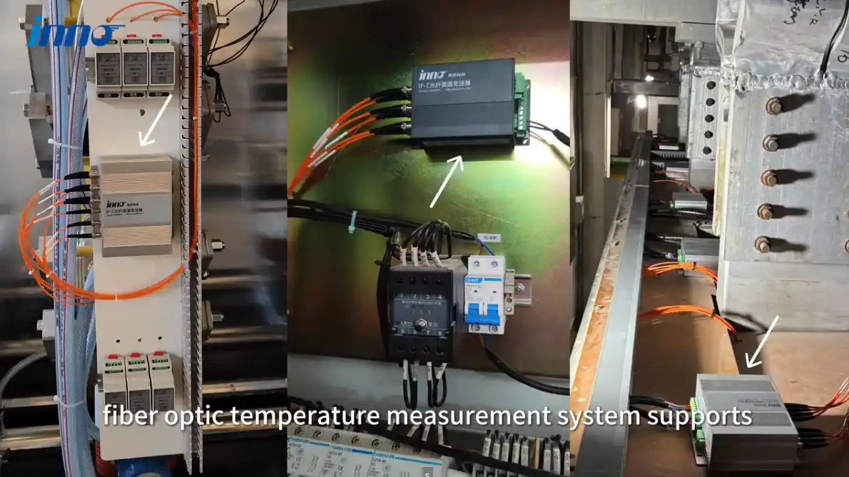
INNO's technology is fluorescence-based point fiber optic temperature sensing. The probe has a sensing tip, and the temperature is measured at that tip. An optical fiber carries the excitation light to the tip and the return signal back to a compatible instrument, which converts it into a temperature value.
Each probe measures one defined physical location. The fiber between the sensing tip and the instrument carries the signal but does not measure temperature along its length. This is point sensing, not distributed sensing, and a probe does not automatically find an unknown hot spot. The measurement point has to be chosen in advance.
For windings, a motor winding fiber optic temperature probe is installed with its sensing tip at a selected winding location. The general construction and range of probe types are described on the page for fiber optic temperature sensors.
Characteristics relevant to motor applications include:
- Electrical isolation of the optical sensing path
- High resistance to electromagnetic interference
- Suitability for selected high-voltage or strong electromagnetic-field environments
- Small probe geometry, which can help where installation space is limited
- Multi-point monitoring using multiple independent probes
These are characteristics of the sensing method, not guarantees for every installation. Whether a fiber optic probe fits a particular motor depends on the measurement location, the winding design and the way the fiber can be routed out of the machine.
RTD vs Thermistor vs Thermocouple vs Fiber Optic Sensor
The table below compares the four types by how they work and where they are commonly considered. It is a neutral comparison, not a ranking, and each row reflects general characteristics that vary with the specific product.
| Sensor Type | Measurement Principle | Typical Motor Use | Electrical Signal at Measurement Point | Continuous Temperature Measurement | Main Selection Consideration |
|---|---|---|---|---|---|
| RTD | Resistance changes with temperature | Embedded winding, stator and bearing monitoring | Yes, electrical conductors run to the sensing element | Yes | Lead wiring, insulation and signal routing in the electrical environment |
| Thermistor | Semiconductor resistance changes with temperature | Winding protection and threshold detection, and in some designs temperature readout | Yes, electrical conductors run to the sensing element | Depends on sensor type and control circuit | Whether the purpose is protection or continuous data |
| Thermocouple | Thermoelectric voltage at a junction of dissimilar metals | General industrial measurement, including some motor and equipment locations | Yes, low-level voltage signal on conductors | Yes | Reference junction, grounding and shielding |
| Fiber optic sensor | Optical signal from the sensing tip, such as fluorescence behavior | Direct measurement at selected winding points, including electrically demanding environments | No, the signal path at the measurement point is optical | Yes | Point placement, fiber routing and compatible instrument channels |
Where Are Temperature Sensors Installed in an Electric Motor?
The measurement location often narrows the choice of sensor before any other factor is considered, because different locations have different objectives.
Stator Windings
The stator winding is a main location for motor temperature monitoring. Sensors are embedded in or placed at selected winding locations, usually during manufacturing. A stator temperature sensor of any type measures only where it is installed, so the position relative to the winding matters as much as the sensor type.
Bearings
Bearing temperature monitoring has a different objective from winding monitoring. It is concerned with lubrication and mechanical condition, and RTDs are commonly used there. Fiber optic sensing is not required for bearings in general, and the choice depends on the same factors as elsewhere: location, environment and monitoring system.
Motor Housing
Housing or surface temperature is easier to access, but it does not directly equal internal winding temperature. The difference depends on the motor design, load and cooling. Housing measurements can be useful for other purposes, but they are not a substitute for a sensor at the winding.
Other Internal Locations
Depending on the motor design, other internal locations may be of interest, such as slots, end windings or other thermal locations. Which of them are accessible for sensor placement depends on the construction, and no general rule applies to every motor.
Why Winding Temperature Matters
Winding temperature reflects the combined effect of current, losses, load, cooling, ambient conditions and airflow. When load current increases, winding losses generally increase and so does heat generation. If cooling or airflow is restricted, the same load can produce a higher winding temperature. A sensor at the winding captures the result of all of these together, which surface measurements cannot do.
Acceptable temperature values depend on the motor design, insulation system and the applicable specification, so they should be taken from the motor documentation and not from general figures. The measurement methods themselves, including winding resistance and surface techniques, are covered in our article on how motor winding temperature is measured. This article focuses on choosing the sensor for a given measurement point.
Monitoring Multiple Motor Temperature Points
A single point sensor gives one temperature value at one location. Where several locations matter, each needs its own sensor. With fiber optic point sensing, one defined point corresponds to one probe and one compatible active channel on the instrument.
As a configuration example, monitoring three independent winding locations would normally need three probes and at least three compatible active channels. This is only an example. The number of measurement points depends on the motor design and the monitoring objective, and not every motor needs three.
Multiple probes give multiple independent point measurements, not a distributed temperature profile. Multi-channel instruments are described on the page for fiber optic temperature monitoring systems, and the broader application context is covered under motor and generator temperature monitoring.
How to Choose an Electric Motor Temperature Sensor
Work through the following points in order. Each one narrows the options.
- Measurement location: winding, stator, bearing, housing or another internal point.
- Expected temperature range: confirm against the sensor documentation.
- Required response behavior: how quickly the reading needs to follow changes.
- Required measurement accuracy: as stated in the specification, and confirmed for the chosen sensor.
- Electrical isolation requirement: whether conductive wiring at the measurement point is acceptable.
- Electromagnetic environment: high voltage, strong fields or high-frequency conditions.
- Available installation space: the room at the intended measurement point.
- Sensor diameter and geometry: whether the probe fits the location.
- Cable or fiber routing: how the connection leaves the motor and reaches the instrument.
- Number of measurement points: each independent location needs its own sensor.
- Required monitoring channels: enough compatible input channels for all sensors.
- Control, PLC or monitoring interface: the signal type the existing system accepts.
Sensor Selection by Application Condition
The table lists sensor types commonly considered for typical conditions, together with the question that decides between them. It does not exclude other options.
| Application Condition | Sensor Types Commonly Considered | Key Question |
|---|---|---|
| Embedded stator winding monitoring | RTD, thermistor, thermocouple, fiber optic | Does the monitoring system accept the signal type, and is the location accessible during manufacturing? |
| Motor protection threshold | Thermistor, RTD | Is a switching function enough, or is continuous temperature data needed? |
| General industrial temperature measurement | RTD, thermocouple | What range and interface does the application need? |
| High-voltage motor winding | RTD, fiber optic | How are insulation and electrical isolation at the measurement point handled? |
| Strong electromagnetic environment | Shielded electrical sensors, fiber optic | Can wiring and shielding keep the electrical signal reliable, or is an optical path preferred? |
| Multi-point winding monitoring | RTD, fiber optic | How many independent points are needed, and are enough channels available? |
| Bearing monitoring | RTD, thermocouple | What mounting and interface does the bearing location allow? |
Temperature Measurement in High-Voltage and Strong EMI Environments
Electrical sensors rely on conductive wiring and electrical signals. In many motors this works well, but in high-voltage machines or where strong electromagnetic fields are present, the wiring becomes part of the design problem. Insulation, grounding, shielding and cable routing all need attention, and the signal has to remain reliable in the presence of the field.
Fiber optic sensing uses an optical path between the sensing point and the instrument. There is no conductive signal path at the measurement point, so in some high-voltage, strong-field or radio-frequency environments this can simplify electrical isolation and signal routing. This is a statement about the sensing method, not a claim of complete immunity. Fiber optic probes show high resistance to electromagnetic interference, and the actual result still depends on the installation.
New Motor Design vs Retrofit Temperature Monitoring
In a new motor, embedded sensors can be planned during design and manufacturing. Measurement points can be agreed, sensors placed while the winding is accessible, and the routing of wires or fibers built into the construction.
In an existing motor, internal winding access is usually limited. Options may include existing embedded RTDs, bearing sensors, surface measurement or other accessible internal points. It should not be assumed that a fiber optic probe can always be retrofitted into an existing winding, and each case needs an engineering review.
Common Sensor Selection Mistakes
- Choosing a sensor before defining the measurement location.
- Treating housing temperature as winding temperature.
- Assuming one sensor represents the entire winding.
- Ignoring electrical isolation requirements at the measurement point.
- Ignoring cable or fiber routing until late in the design.
- Using a protection thermistor when continuous temperature data is required.
- Assuming multiple point probes provide distributed sensing.
Conclusion
Electric motors can use RTDs, thermistors, thermocouples and fiber optic sensors, but they serve different measurement and protection objectives. RTDs support continuous electrical resistance-based monitoring. Thermistors provide compact sensing and protection functions. Thermocouples cover broad industrial temperature measurement. Fiber optic sensors provide direct point measurement using an electrically isolated optical signal path.
Sensor selection starts with the measurement point and the operating environment, not with the sensor name. Once the location, temperature range, electrical conditions and monitoring interface are defined, the suitable options usually become clear.
If a motor project requires direct winding temperature measurement, INNO can help review the measurement points, probe configuration, fiber routing and channel requirements.