
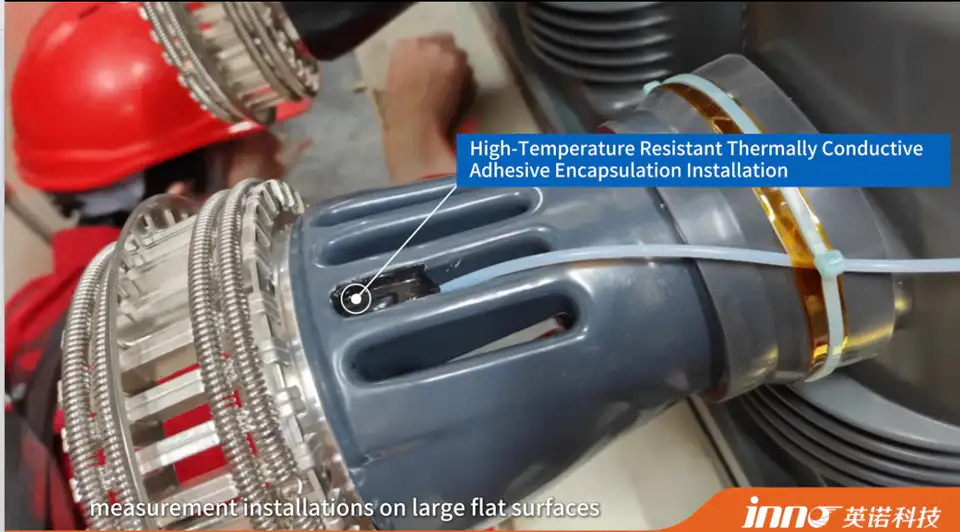
Fiber optic temperature probes can be installed using several mechanical mounting methods depending on the sensing point, surface geometry, operating temperature and whether the probe must be removable. Common mounting options include cable ties, high-temperature tape, thermally conductive adhesive, UT / OT connector mounting and clamps.
The goal is not simply to hold the fiber in place. The sensing tip should remain in stable contact with the intended measurement point while the fiber is routed without unnecessary tension, crushing or sharp bends. This guide focuses on fluorescence-based point fiber optic temperature sensing, where one probe measures one defined physical temperature point.
There is no single mounting method that is best for every application.
Key Takeaways
- Probe mounting should keep the sensing tip stable at the intended measurement point.
- Good thermal contact is important for representative point temperature measurement.
- Cable ties are simple and practical where a suitable structure is available.
- High-temperature tape is useful for lightweight surface fixation.
- Thermally conductive adhesive provides a more permanent bonded installation.
- Connectors and clamps provide more structured mechanical fixation where equipment design allows.
Why Does Probe Mounting Matter?
A fiber optic temperature probe measures the temperature at the exact physical location of the sensing tip. Unstable mounting can lead to sensor movement, changing contact pressure, inconsistent thermal contact, probe displacement, or mechanical strain on the fiber.
Poor or inconsistent mounting does not automatically cause inaccurate readings in every case, but it can make the measured temperature less representative of the intended point.
What Should Be Checked Before Installing a Fiber Optic Temperature Probe?
Before installation, confirm the exact measurement point, surface shape, surface material, expected operating temperature, available mounting space, probe diameter, fiber routing direction, whether the installation must be removable, whether adhesive is acceptable, whether a connector or clamp can be mechanically fixed, and the required fiber length.
Mounting method should be selected after the sensing point is defined, not before.
Method 1: Cable Tie Mounting
Cable ties can be used where the probe needs to be fixed against a cable, pipe, winding structure, bracket or other suitable support. This method is simple, quick and removable, making it useful for prototypes, temporary testing and accessible equipment installations.
Do not overtighten around the optical fiber. Fix the probe body or protected section where appropriate, keep the sensing tip positioned at the intended point, and avoid crushing or sharply bending the fiber. For elevated temperatures, the tie material itself must be suitable for the operating environment.
Method 2: High-Temperature Tape Wrapping
High-temperature tape can hold the probe against a surface or structure where a lightweight and low-profile mounting method is preferred. This suits flat or gently curved surfaces, test setups, limited installation space, and temporary or semi-permanent mounting.
Advantages include a low profile, easy application, minimal additional mechanical structure and the ability to follow gently curved or irregular surfaces. Consider the tape's temperature rating, adhesion to the target surface, surface cleanliness, tape aging, and maintaining direct probe contact. Use high-temperature tape suitable for the application rather than a general-purpose tape.
Method 3: Thermally Conductive Adhesive Encapsulation
Thermally conductive adhesive can bond the sensing tip or probe structure to a selected measurement point. This suits permanent or long-term installation, locations requiring stable probe position, surfaces where mechanical clips are difficult to use, and applications requiring repeatable probe-to-surface contact.
Advantages include stable fixation, good mechanical retention, and improved contact between the probe and target. The adhesive itself becomes part of the thermal path, so adhesive thickness, curing, operating temperature, compatibility with the target material, and future probe replacement should all be considered. More adhesive does not mean better measurement.
Method 4: UT / OT Connector Mounting
UT / OT connector-style fixation can provide a defined mechanical termination or attachment point where the equipment structure supports this installation method. This offers structured mechanical attachment, a repeatable connection point, convenient equipment integration, and suitability where bolted or terminal-style attachment is available.
In this context, the connector functions as a mechanical mounting and positioning method for the probe assembly, not as an electrical temperature-signal connector. Mechanical compatibility with the equipment structure should be confirmed according to the probe specification.
Method 5: Clamp Mounting
A clamp provides mechanical pressure and stable positioning without permanently bonding the probe to the target. This suits busbars, conductive bars, mechanical structures, test fixtures, and flat or cylindrical surfaces where clamp geometry permits.
Advantages include stable mechanical fixation, removability, repeatable positioning, and no adhesive curing required. Consider clamp pressure, probe protection, geometry, vibration, clearance, and avoiding fiber crushing during installation.
5 Fiber Optic Temperature Probe Mounting Methods Compared
| Mounting Method | Installation Type | Removable | Typical Fixation Characteristic | Typical Use | Main Consideration |
|---|---|---|---|---|---|
| Cable Tie | Mechanical | Yes | Simple removable fixation | Cables / structures / accessible equipment | Avoid excessive tightening |
| High-Temperature Tape | Surface fixation | Usually | Low-profile surface fixation | Flat surfaces / test setups / limited space | Tape temperature and adhesion |
| Thermally Conductive Adhesive | Bonded | Usually no | Bonded long-term fixation | Permanent surface measurement | Adhesive layer and curing |
| UT / OT Connector | Mechanical connection | Yes | Defined mechanical attachment | Defined mounting / terminal-style structures | Mechanical compatibility |
| Clamp | Mechanical | Yes | Stable removable fixation | Busbars / structures / fixtures | Pressure and probe protection |
These are general comparisons rather than an absolute ranking system.
How Do You Choose Between the 5 Mounting Methods?
Use cable ties when simple mechanical support is available, the installation should remain removable, and low-complexity mounting is preferred. Use high-temperature tape when space is limited, a low-profile mounting method is needed, and the target surface allows tape fixation.
Use thermally conductive adhesive when permanent installation is acceptable and a stable long-term probe position is required. Use UT / OT connector mounting when the equipment provides a suitable mechanical attachment point and a repeatable mechanical connection is preferred. Use clamp mounting when stable removable fixation is needed and the structure can accept a clamp.
Permanent vs Removable Probe Installation
Thermally conductive adhesive and some tape installations tend to be more permanent or semi-permanent, while cable ties, connectors and clamps are generally removable. Actual removability still depends on the specific installation and structure involved.
Selection should account for serviceability, probe replacement, equipment maintenance, long-term monitoring needs, and temporary testing requirements.
How Important Is Thermal Contact?
A fiber optic probe measures temperature at its sensing tip. For the measurement to represent the target location, the probe tip should have stable and appropriate thermal contact with the measurement point.
Contributing factors include surface contact, air gaps, mounting pressure, adhesive layer, surface geometry and probe orientation. Perfect thermal contact is not guaranteed in every installation, and the practical effect on measurement will vary by application.
How Should the Fiber Be Routed After the Probe Is Mounted?
After mounting, fiber routing is equally important. Avoid unnecessary tension, crushing, sharp bends and contact with moving parts. Provide mechanical support where necessary, route the fiber toward the feedthrough or monitoring instrument, and keep excess fiber controlled.
Follow the bend-radius requirement specified for the selected probe and fiber assembly rather than an assumed value.
How Much Fiber Length Is Needed?
Fiber length should follow the route from the sensing point to the equipment exit, the feedthrough route, the external route to the monitoring instrument, and an installation allowance. Typical INNO point-probe configurations can support approximately 0-20 m depending on probe design and project requirements, and 3-5 m can be a practical starting reference for many equipment applications.
The final length should follow the actual routing rather than a default value. More detail is available in a dedicated guide on choosing the right fiber length for a fiber optic temperature sensor.
Installing Fiber Optic Temperature Probes on Transformers
For oil-immersed transformers, probe placement is typically integrated during transformer manufacturing at selected winding locations. For dry-type transformers, probes may be positioned at selected winding or equipment locations depending on construction.
Cable tie or tape methods used on accessible equipment cannot simply be applied to internal transformer windings. Placement and fixation for internal winding measurement must follow the transformer manufacturer's design, insulation system and mechanical construction, as covered in more detail in a related article on where fiber optic temperature sensors are placed in transformer windings.
Installing Fiber Optic Probes on Switchgear and Busbars
Switchgear and busbar installations may involve busbar surfaces, joints, cable terminations and connection points. Depending on equipment geometry and electrical clearance requirements, mounting may use a clamp, cable tie, adhesive, or a suitable mechanical connector.
Specific high-voltage clearance distances should follow the applicable equipment design and safety requirements rather than a general reference figure.
Installing Probes in RF and Microwave Heating Equipment
In RF and microwave heating equipment, installation typically focuses on sensing-point access, a non-conductive probe path, chamber entry, fiber routing and mechanical fixation. Depending on the chamber and target material, mounting may use tape, adhesive, a clamp or a suitable mechanical fixture.
A dedicated article covers temperature measurement inside RF and microwave heating equipment in more depth.
Installing Probes in Motors and Generators
Depending on machine construction, probes may be attached or integrated at selected winding, stator or structural measurement points. Installation should account for mechanical stability, vibration, available space, fiber routing and insulation requirements.
There is no single fixed measurement point that applies to every motor or generator design.
Does the Mounting Method Affect Temperature Response?
Yes, the mounting method can influence how quickly the sensing tip reaches the target temperature because the mechanical interface becomes part of the thermal path. Contributing factors include probe contact, adhesive layer, tape layer, surface geometry, thermal mass, airflow and target material.
No single mounting method is always the fastest for every application. A typical INNO point probe may respond in under 1 second, depending on probe configuration, but the actual installed response also depends on mounting and process conditions.
Can the Same Mounting Method Be Used for Every Application?
No. Different applications involve different surface geometry, temperature, vibration, insulation, available space, maintenance requirements, need for removal, and thermal contact requirements.
Mounting method should be selected for the measurement point, not simply based on convenience.
Common Fiber Optic Temperature Probe Installation Mistakes
- Mounting near the desired point instead of at the actual sensing point. This reduces how representative the measured temperature is of the intended location.
- Overtightening a cable tie or clamp. Excessive force can stress the probe or fiber without improving measurement.
- Leaving unstable thermal contact. Inconsistent contact can make the reading less representative of the target point.
- Using tape or adhesive that is not suitable for the operating temperature. Material degradation can compromise fixation over time.
- Applying excessive adhesive around the sensing tip. This can add unnecessary thermal mass to the measurement path.
- Creating unnecessary tension in the fiber. Tension can stress the fiber and its connections.
- Routing the fiber with sharp bends. Follow the bend-radius requirement specified for the selected probe and fiber assembly.
- Ignoring future probe replacement requirements. Installation choices should account for maintenance access where relevant.
Fiber Optic Temperature Sensor Installation Checklist
- Confirm the exact sensing point
- Confirm expected temperature range
- Select mounting method
- Check probe dimensions
- Check target surface geometry
- Confirm thermal contact
- Protect sensing tip
- Avoid excessive mechanical pressure
- Plan fiber routing
- Confirm fiber length
- Confirm chamber / enclosure entry
- Provide strain relief where needed
- Confirm monitoring instrument position
- Check whether probe needs future replacement
- Inspect installation before operation