
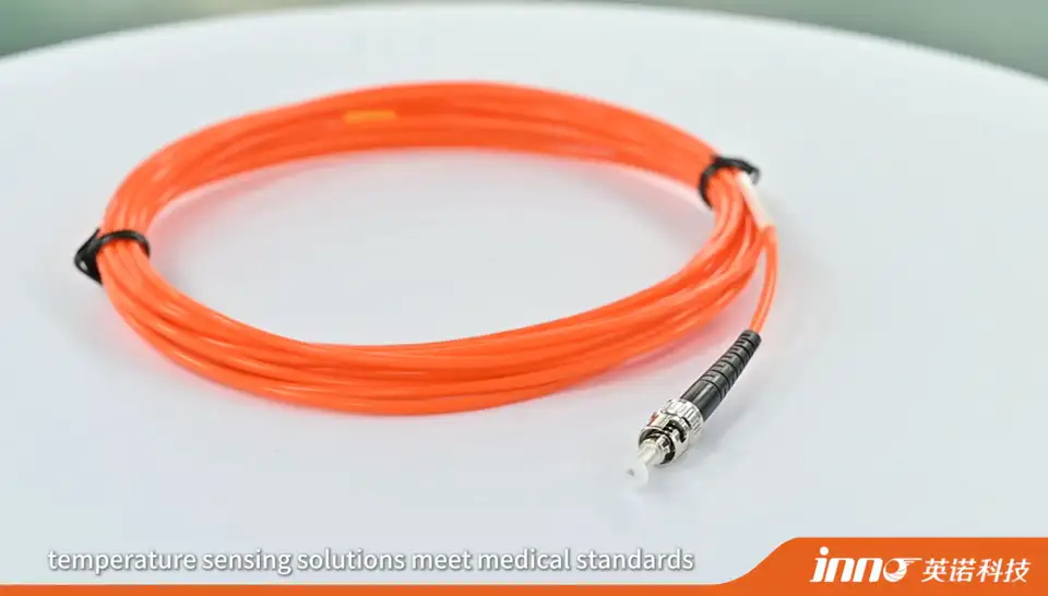
Temperature inside RF and microwave heating equipment can be measured using fiber optic temperature probes, infrared sensors, conventional electrical sensors where the equipment design allows, or other application-specific measurement methods.
When the sensor must operate directly inside a strong RF or microwave field, fiber optic temperature sensing is often considered because the probe uses a non-conductive optical signal path and does not rely on metallic electrical measurement leads at the sensing point. Infrared measurement can be practical for visible surfaces, while fiber optic probes are commonly used for direct contact or embedded point measurement where optical access for infrared is limited.
This guide focuses on fluorescence-based point fiber optic temperature sensing, where one probe measures one defined physical temperature point and the optical signal path carries no conductive electrical measurement wiring. The correct method for a given system depends on the measurement location, the RF or microwave field, chamber design, target material, whether surface or internal measurement is needed, continuous or temporary monitoring, required electrical isolation, probe access, and the monitoring instrument location.
Key Takeaways
- Fiber optic probes are commonly considered for direct temperature measurement inside strong RF and microwave fields.
- The optical sensing path does not require conductive electrical measurement leads at the sensing point.
- Infrared sensors are useful for accessible surfaces with a clear line of sight.
- PT100 and thermocouples can still be used where equipment design and electromagnetic conditions allow.
- Probe location and fiber routing are as important as the selected sensor type.
- One point fiber optic probe measures one defined temperature location.
Why Is Temperature Measurement Inside RF and Microwave Equipment Different?
Measurement inside RF and microwave equipment involves practical considerations such as strong electromagnetic fields, metallic sensor interaction, conductive lead routing, limited chamber access, line-of-sight restrictions, moving or enclosed test objects, and the difference between internal and surface temperature.
Conventional electrical sensors may require additional consideration because conductive probes or leads can interact with the RF or microwave environment depending on system design. This does not mean metal sensors cannot be used - it means the installation needs to account for the electromagnetic environment.
What Temperature Measurement Methods Can Be Used?
| Method | Measurement Type | Signal Path | Best Suited For | Main Consideration |
|---|---|---|---|---|
| Fiber Optic Temperature Sensor | Direct contact / embedded point | Optical | Internal or selected RF / microwave measurement points | Requires physical probe access |
| Infrared Sensor | Non-contact surface | Optical | Visible and accessible surfaces | Requires line of sight |
| PT100 / RTD | Direct contact | Electrical | Conventional equipment where conductive wiring is acceptable | Lead routing and electromagnetic environment |
| Thermocouple | Direct contact | Electrical | Industrial heating where installation permits | Conductive junction and lead behavior |
Why Are Fiber Optic Temperature Sensors Used in RF and Microwave Fields?
Fiber optic sensors are commonly used in RF and microwave fields because the optical sensing path is non-conductive, provides electrical isolation, resists RF and EMI interference along the optical path, supports direct point measurement, and allows the monitoring instrument to be located outside the active field where required.
Fiber optic sensing is not always required for every RF or microwave application. It is particularly useful when direct measurement is needed inside the active field and conductive sensor wiring is undesirable.
How Does a Fiber Optic Temperature Probe Measure Inside a Microwave Chamber?
The measurement sequence is straightforward: the probe tip is positioned at the selected temperature point, temperature affects the sensing material, the optical response travels through the fiber, and the monitoring instrument converts the optical signal into a temperature reading.
This is point temperature measurement. One probe measures one defined physical location, not the entire chamber or process.
Can PT100 Sensors Be Used Inside Microwave Heating Equipment?
Sometimes, depending on equipment design and RF or microwave conditions. PT100 sensors use electrical resistance measurement with conductive leads, so installation needs to account for lead routing, field interaction, shielding, grounding, electrical isolation and sensor construction.
PT100 sensors are not automatically excluded from microwave equipment - suitability depends on how the specific system is designed and installed.
Can Thermocouples Be Used in Microwave Heating?
They can be used in some systems, but the conductive junction and leads require careful consideration in an RF or microwave field. Potential issues can include electromagnetic coupling, induced signals, lead interaction and routing constraints.
Behavior depends on equipment design, field distribution and installation rather than being a fixed outcome for every thermocouple application.
Fiber Optic vs PT100 vs Thermocouple vs Infrared in Microwave Heating
| Method | Contact / Non-Contact | Conductive Sensor Path | Works for Internal Points | Line of Sight Needed | Main Use |
|---|---|---|---|---|---|
| Fiber Optic | Contact / embedded | No conductive measurement path | Yes | No | Direct point measurement |
| PT100 | Contact | Yes | Yes | No | Conventional contact measurement |
| Thermocouple | Contact | Yes | Yes | No | Industrial process measurement |
| Infrared | Non-contact | No target wiring | Usually surface | Yes | Surface monitoring |
Direct Contact vs Non-Contact Temperature Measurement
Direct contact measurement means the sensor physically touches or is embedded in the target, which suits internal material temperature, a product core or selected internal point, and continuous fixed-point monitoring. Non-contact measurement, typically infrared, suits a visible surface, a moving object, temporary inspection, or situations where probe contact is not practical.
Neither approach is universally better - the choice depends on whether the required measurement point is internal or on an accessible surface.
Where Should the Temperature Probe Be Placed?
Placement depends on the heating target, expected hot zone, process objective, chamber geometry, probe entry point, product position and material structure.
The probe measures only the location where its sensing tip is installed. One sensor does not automatically represent the whole chamber, and there is no fixed placement position that applies to every microwave or RF system.
How Should the Fiber Be Routed Through a Microwave Chamber?
Routing should account for the sensing point, chamber entry, feedthrough, bend path, moving components, mechanical protection and monitoring instrument location.
Fiber routing should follow the actual equipment geometry, maintain suitable mechanical protection, and avoid unnecessary excess fiber inside the chamber.
How Far Can the Monitoring Instrument Be from the Microwave Equipment?
Fiber length allows the monitoring instrument to be installed outside or away from the active RF or microwave area where required. Typical fiber configurations support approximately 0-20 m depending on probe structure and project requirements, and 3-5 m can be a practical starting reference for many equipment applications.
The actual length should follow the real routing path rather than a fixed default. Selection considerations are covered in How to Choose the Right Fiber Length for a Fiber Optic Temperature Sensor?
Can Multiple Temperature Points Be Monitored Inside Microwave Equipment?
Yes. One point fiber optic probe normally corresponds to one measurement channel, and multiple points can cover several positions in one chamber, inlet and outlet areas, different material locations, several test samples, or multiple heating zones.
For special projects, approximately 1-64 channels may be configurable depending on the monitoring instrument and project requirements, though not every model supports this full range. Channel planning is discussed further in How Many Channels Do You Need for Fiber Optic Temperature Monitoring?
Multi-Point Temperature Monitoring in RF and Microwave Heating
Heating is not always uniform across a chamber or process. Multiple measurement points can help compare different regions, different samples, different process stages, or multiple heating zones.
A multi-point fiber optic system still provides multiple discrete point measurements, not a complete temperature distribution across the entire volume.
Temperature Measurement in Industrial Microwave Heating
Industrial microwave heating applications include microwave drying, microwave curing, dielectric heating, material processing and general thermal treatment. Continuous point monitoring may be useful when the internal product temperature is more important than the external chamber temperature.
Temperature Measurement in RF Heating Equipment
RF heating and dielectric heating systems can also create electromagnetic environments where conductive sensor wiring requires additional consideration. Fiber optic probes can support direct point sensing, electrical isolation and separation of the monitoring instrument from the active field.
RF and microwave heating both use electromagnetic energy, but equipment frequency, geometry and field distribution differ, so sensor suitability should be checked for the actual system rather than assumed to be identical.
Laboratory RF and Microwave Temperature Measurement
Laboratory environments such as test chambers, material testing setups, RF research and dielectric heating experiments may need interchangeable probes, different fiber lengths, multiple channels and a remote monitoring unit. Specific experimental safety values should follow the applicable laboratory procedures for the equipment in use.
Does RF or Microwave Energy Affect Fiber Optic Temperature Measurement?
The optical sensing path is inherently immune to electromagnetic interference, unlike conductive electrical signal wiring that can require additional shielding, grounding or routing control. The complete measurement system, however, still includes the monitoring instrument and its electrical interfaces outside the optical sensing path.
This means the optical measurement path resists RF and EMI effects, not that the entire installation is completely immune to all interference at every point.
Does Fiber Length Affect Microwave Temperature Measurement?
Fiber length is mainly a routing parameter within the supported sensor configuration, not a microwave temperature range parameter. Within the supported configuration, longer fiber does not automatically mean slower thermal response.
Response is more closely related to the probe tip, thermal contact, probe structure, target material and process conditions.
How Fast Can a Fiber Optic Temperature Sensor Respond?
Typical INNO point-probe response is under 1 second, depending on probe structure and measurement conditions. Actual process response is also affected by probe contact, material thermal properties, installation and sensing tip design, so this figure should be treated as a typical reference rather than a fixed value for every setup.
What Temperature Range Can Be Measured?
Typical INNO point-probe configurations cover approximately -40 to 260 C, with accuracy of approximately +/-0.5 to +/-1 C, depending on probe configuration. This article focuses on temperature measurement methods rather than detailed range specifications, so treat these figures as typical reference values.
How to Choose a Temperature Sensor for RF and Microwave Heating
Practical selection factors include:
- Measurement point
- Internal or surface temperature
- RF / microwave environment
- Contact or non-contact measurement
- Temperature range
- Probe diameter
- Probe material / structure
- Fiber length
- Number of sensing points
- Number of channels
- Chamber entry / feedthrough
- Monitoring instrument location
- Communication requirement
RF and Microwave Temperature Measurement Selection Guide
| Measurement Requirement | Practical Direction |
|---|---|
| Internal point inside active microwave field | Fiber optic temperature probe |
| Visible product surface | Infrared sensor |
| Conventional contact measurement outside strong RF field | PT100 / RTD may be suitable |
| Industrial process with suitable electrical installation | Thermocouple may be suitable |
| Multiple internal measurement points | Multi-channel fiber optic monitoring |
| Remote instrument outside chamber | Fiber optic probe with suitable fiber length |
Final sensor selection should follow the actual equipment design, field environment and measurement objective.
What Information Is Needed Before Selecting a Microwave Temperature Sensor?
- Equipment type
- RF or microwave heating
- Measurement point
- Target material
- Internal or surface measurement
- Required temperature range
- Expected operating temperature
- Probe diameter
- Probe structure
- Fiber length
- Chamber dimensions
- Probe entry point
- Number of sensing points
- Required channels
- Monitoring instrument location
- Continuous or temporary monitoring
- Required communication interface
- PLC / SCADA requirement
Common RF and Microwave Temperature Measurement Misunderstandings
Any metallic temperature sensor can always be placed directly in a microwave field. Suitability depends on system design, field distribution and sensor construction.
PT100 and thermocouples can never be used in RF or microwave equipment. They can be used in suitable systems when the installation is properly designed.
Infrared measures internal material temperature. Infrared generally measures accessible surface temperature unless a specific optical arrangement supports another measurement geometry.
One fiber optic probe measures the whole microwave chamber. One point probe measures one defined physical location.
Fiber optic sensors are selected only because they are more accurate. Electrical isolation, non-conductive sensing and RF / EMI immunity are often the more important reasons.