
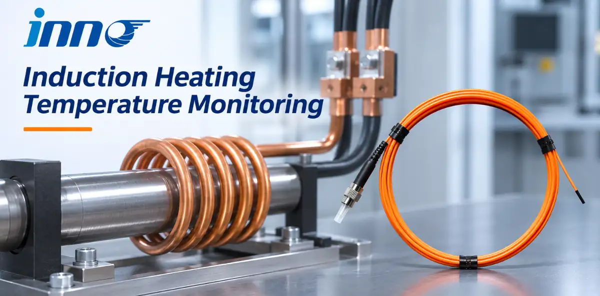
- Fluorescent fiber optic sensors monitor temperature at selected points around induction heating equipment through an electrically isolated optical path.
- The probes are immune to electromagnetic interference, supporting reliable readings near induction coils, copper joints, busbars, and connected equipment.
- Multiple probes connect to a compatible multi-channel instrument for simultaneous temperature monitoring.
- Compact probes and flexible fiber routing make it practical to monitor several locations across an induction heating setup.
Induction heating uses an alternating magnetic field to heat metal. Coil terminals, copper connections, busbars, and nearby components are key temperature monitoring points around the equipment. Fluorescent fiber optic sensors provide direct readings at these locations while keeping the sensing path electrically isolated.
Fiber Optic Temperature Measurement Points
Fiber optic probes are installed at defined points around induction heating equipment. Common locations include coil terminals, bolted copper joints, busbars, and fixtures or machine components near the coil.
Induction Coil Terminals and Copper Joints
Coil terminals and bolted copper joints carry current as the induction system operates. A fiber optic probe placed at a selected connection provides a direct temperature reading at that point, with electrical isolation and immunity to electromagnetic interference.
Nearby Equipment and Tooling
Fiber optic probes can also monitor fixtures, tooling, and machine components around the heating station. The readings help operators follow temperature changes at the locations that matter to the process and equipment.
EMI-Immune Temperature Sensors for Induction Heating
The electromagnetic field around an induction coil makes interference immunity a key feature of the temperature measurement system. Fluorescent fiber optic probes use a non-conductive optical path, keeping the sensing point electrically isolated while delivering temperature readings in the strong field around the equipment.
This sensing principle is also useful in other strong-field environments. For example, fiber optic temperature measurement in strong electromagnetic fields uses the same combination of optical sensing and electrical isolation.
Temperature Sensor Comparison for Induction Heating
Each sensor type is suited to particular measurement points in an induction heating system.
| Measurement method | Common measurement point | Typical use |
|---|---|---|
| Infrared pyrometer | Hot or moving workpiece | Contact-free surface temperature measurement during heating |
| Thermocouple | Accessible tooling or machine component | Contact measurement at a defined point |
| Fluorescent fiber optic probe | Coil terminal, copper joint, or component near the coil | Electrically isolated, EMI-immune point temperature monitoring |
Electrically Isolated Monitoring for Coil Connections
At coil terminals, copper joints, and nearby components, fiber optic probes provide point measurements without a conductive sensing path at the measurement location. Fluorescent probes connect to compatible fiber optic temperature sensors and temperature monitoring systems for display and data collection.
Multi-Point Fiber Optic Temperature Monitoring
Several probes can monitor coil terminals, copper connections, tooling, or other selected locations at the same time. A multi-channel instrument presents readings together, making it easier to compare temperatures as heating power and operating conditions change.
For installations with multiple measurement points, multi-point temperature monitoring combines the probes and channels into one coordinated arrangement. A compatible multi-channel fiber optic temperature transmitter collects the readings for local display or system integration.
Flexible Fiber Optic Probe Installation
- Mark the monitoring points. Identify coil terminals, copper joints, busbars, and nearby components on an equipment diagram.
- Plan probe placement. Specify the sensing-tip location and mounting arrangement for each point.
- Route the optical fibers. Plan a path from each probe to the monitoring instrument and identify the corresponding channel.
- Connect and label the channels. Match each probe connection to its point on the equipment diagram.
- Review readings during operation. Compare temperatures across selected points as the heating process runs.
Compact sensing tips, optical fiber routing, and multi-channel instruments let engineers build a monitoring layout around the equipment and the locations they need to observe.
Fiber Optic Temperature Sensor Advantages
Fiber optic temperature measurement brings several useful capabilities to induction heating equipment:
- EMI immunity: The optical sensing path delivers readings in the electromagnetic environment around induction coils.
- Electrical isolation: The non-conductive probe and fiber separate the sensing point from the monitoring instrument.
- Multi-point monitoring: Multiple probes can connect to a multi-channel instrument for simultaneous readings.
- Installation flexibility: Compact probe tips and fiber routing support measurement at different points around the equipment.
- System integration: Compatible instruments connect temperature readings with display, alarm, and communication functions.
A monitoring layout starts with the points to be measured, probe positions, fiber routes, and the number of channels. Talk with INNO's engineering team about configuring a fiber optic system for your induction heating equipment.
Frequently Asked Questions
How can induction heating equipment temperature be monitored?
Install fiber optic probes at selected points such as coil terminals, copper joints, busbars, or nearby machine components. Connect them to a compatible monitoring instrument to view temperatures during operation.
How can coil connections be monitored?
Place fiber optic probes at selected coil terminals or copper connections. Their optical sensing path provides electrically isolated, EMI-immune readings at those points.
Why use a fiber optic temperature sensor near an induction heater?
Fluorescent fiber optic probes are immune to electromagnetic interference and provide an electrically isolated sensing path, making them well suited to temperature monitoring near induction equipment.
Can several points be monitored at the same time?
Yes. A compatible multi-channel instrument can collect readings from several fiber optic probes simultaneously. Assign channels to the planned measurement points for clear monitoring.