
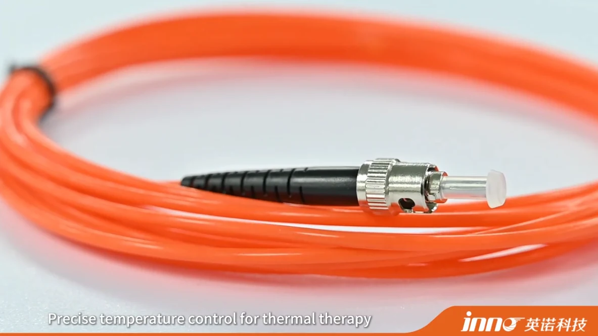
Fiber optic solutions for temperature monitoring are most useful when the measurement point creates problems for conventional electrical sensors. Typical examples are high voltage, strong electromagnetic fields, restricted internal access, RF or microwave energy, and the need for electrically isolated point temperature measurement. In these cases, optical fiber temperature sensing solutions place a small fiber optic temperature sensor at the point of interest and keep the electronic instrument away from it.
Fiber optic temperature monitoring is particularly useful where conventional electrical sensors face constraints such as high voltage, strong electromagnetic fields, RF or microwave energy, strong magnetic fields, or limited access to the measurement point. INNO uses fluorescence-based point sensing, where each probe measures one defined physical location and the optical fiber carries the signal to a monitoring instrument. Probe structure, fiber routing, channel count, and system integration therefore vary with the equipment and measurement objective.
Key Takeaways
- Fiber optic temperature monitoring is especially relevant where electrical isolation or strong EMI resistance is useful.
- One probe measures one defined physical point. One sensing tip is one measurement location.
- Different applications need different probe structures and mounting approaches.
- Multiple points require multiple probes and compatible active channels. This is not distributed temperature sensing.
- Instrument location and fiber routing are part of the solution design, not afterthoughts.
- Not every application requires fiber optic sensing. Conventional sensors remain practical in many cases.
- Selection should start from the physical measurement point rather than from the sensor model.
What Is a Fiber Optic Temperature Monitoring Solution?
A solution is more than a sensor. Depending on project scope, it can include:
- a fiber optic probe
- optical fiber
- extension fiber where required
- feedthrough or mechanical installation components
- a temperature transmitter or demodulator
- a multi-channel monitoring instrument
- data output
- PLC, SCADA or DAQ integration
Not every project requires every component. A single-point laboratory test may need only a probe and a compatible instrument, while a multi-point installation in electrical equipment may also involve routing hardware and system integration. The overall approach is introduced under fiber optic temperature measurement.
The sections below follow the same structure: the measurement challenge, what needs to be measured, why fiber optic sensing may be useful, the typical sensing-point approach and the main configuration questions.
Transformer Winding Temperature Monitoring
Measurement challenge: internal winding temperature cannot be fully represented by external tank or oil measurements.
What needs to be measured: temperature at selected locations inside the winding structure.
Why fiber optic sensing may be useful: the sensing point sits in a high-voltage, high-field environment, and the optical path provides electrical isolation and high resistance to electromagnetic interference. Direct point measurement gives a reading at the location itself rather than an estimate from elsewhere.
Typical sensing-point approach: probes may be embedded at selected winding locations during transformer manufacturing. The locations are selected or thermally critical points defined by the transformer design and thermal analysis. A probe does not find the hottest spot on its own, and one probe does not represent a whole winding.
Main configuration questions:
- Which winding locations are defined as measurement points?
- How many independent points are needed?
- How will each fiber exit the transformer?
Related pages: transformer temperature monitoring and direct hot spot monitoring.
Motor and Generator Winding Temperature Monitoring
Measurement challenge: stator windings in high-voltage machines sit close to strong electromagnetic fields, and the sensing point needs to be isolated from the windings' electrical potential.
What needs to be measured: temperature at selected stator winding locations.
Why fiber optic sensing may be useful: RTDs remain common and practical for many machines, and fiber optic sensing does not replace them. It may be considered when electrical isolation, strong EMI resistance, direct point measurement or a special test environment is the main requirement.
Typical sensing-point approach: embedded sensing during manufacturing is common for winding measurements, with probes placed at defined locations rather than distributed along the whole winding.
Main configuration questions:
- Which winding locations matter for the machine's thermal behavior?
- Can probes be installed during manufacturing, or is access limited?
- How will the fibers be routed out of the machine?
Related page: motor and generator temperature monitoring.
High-Voltage Equipment Temperature Measurement
Measurement challenge: energized components and high-voltage test equipment make it difficult to bring conventional electrical leads to the measurement point.
What needs to be measured: temperature at specific points on or inside electrically demanding equipment.
Why fiber optic sensing may be useful: the optical sensing path allows the electronic monitoring instrument to remain away from the sensing point. The fiber itself carries light rather than an electrical signal.
Typical sensing-point approach: a probe is fixed at the selected point and the fiber is routed to an instrument in a lower-stress location. Fiber optic sensing does not make every high-voltage measurement automatically safe. Suitability still depends on probe construction, insulation design, routing, equipment design and installation method.
Main configuration questions:
- What is the voltage situation at the measurement point and along the fiber route?
- How will the probe be mounted and insulated?
- Where can the instrument be placed?
Related page: high-voltage temperature monitoring.
Switchgear and Electrical Connection Temperature Monitoring
Measurement challenge: electrical connections can be thermal-risk points, and they sit in energized equipment where isolation matters.
What needs to be measured: temperature at specific locations such as busbar joints, bolted connections, selected conductor points or cable termination areas.
Why fiber optic sensing may be useful: the probe can be placed at the connection while the optical path keeps the instrument electrically separated from it.
Typical sensing-point approach: point probes measure selected locations only. They do not continuously monitor entire power cables or a full busbar run. The approach works when the thermal-risk point is known.
Main configuration questions:
- Where is the known thermal-risk point?
- How will the probe be fixed to it?
- How many connections need independent measurement?
- How will the fiber be routed?
Related page: switchgear temperature monitoring.
RF and Microwave Temperature Measurement
Measurement challenge: conductive probes and electrical leads may interact with RF or microwave fields, depending on equipment design.
What needs to be measured: temperature at a defined point in or near the heated material or component.
Why fiber optic sensing may be useful: a fiber optic point probe provides a non-conductive sensing path and direct point measurement, with the instrument located outside the active field where appropriate. This does not mean metal sensors can never be used. Conventional electrical sensors may need additional consideration for routing, grounding, shielding and field interaction.
Typical sensing-point approach: the probe is placed at the selected point and the fiber leaves the field region toward the instrument.
Main configuration questions:
- Where does the measurement point sit relative to the field?
- How will the probe make thermal contact with the target?
- Where does the fiber exit the chamber or cavity?
Related page: microwave temperature monitoring.
MRI and Strong Magnetic Field Temperature Measurement
Measurement challenge: electrical and metallic sensing arrangements can create additional design constraints in strong magnetic-field environments.
What needs to be measured: temperature at a selected location in or near the field.
Why fiber optic sensing may be useful: fiber optic point sensors offer an optical sensing path, electrical isolation and temperature measurement at a chosen location. This article makes no medical or safety-certification claims. Any specific use should be reviewed against verified product information and the requirements of the setup.
Typical sensing-point approach: the probe sits at the target location and the fiber carries the optical signal out of the field to the instrument.
Main configuration questions:
- What space is available at the measurement point?
- How far must the fiber run to reach the instrument?
- What verification does the application require?
Related page: MRI temperature monitoring.
Multi-Point Industrial Temperature Monitoring
Measurement challenge: some equipment has several locations that must be measured independently, such as electrical cabinets, test benches, laboratory equipment and industrial machines.
What needs to be measured: temperature at each defined location, at the same time.
Why fiber optic sensing may be useful: when several points sit in electrically demanding areas, a multi-channel instrument can read multiple isolated optical probes from one location.
Typical sensing-point approach: each point gets its own probe. Multi-point point sensing is not distributed sensing, because each probe measures only its own tip location. As an example, six independent measurement locations would normally need six probes and at least six compatible active channels. This is a configuration example, not a universal standard.
Main configuration questions:
- How many independent locations exist?
- How will each fiber be routed and identified?
- Where will the instrument sit relative to the points?
Related pages: multi-point temperature monitoring and fiber optic temperature monitoring systems.
Laboratory and Test Equipment Temperature Measurement
Measurement challenge: research and test setups often combine unusual geometry with electrical or electromagnetic conditions that complicate conventional sensing.
What needs to be measured: temperature at selected physical points in research equipment, high-voltage tests, thermal experiments, RF tests or electromagnetic test environments.
Why fiber optic sensing may be useful: measurement flexibility. The instrument can be separated from the sensing point, and electrically isolated setups are possible. Custom probe geometry and fiber routing may be options where the application calls for them.
Typical sensing-point approach: probes are placed at the points the experiment defines, and the number of channels follows the number of points.
Main configuration questions:
- Does the test need a particular probe geometry?
- How will the probe be attached and the fiber routed through the setup?
- What data output does the test system need?
Probe structures for these cases are shown in the fiber optic temperature sensors category.
Fiber Optic Temperature Monitoring Solutions at a Glance
| Measurement Environment | Typical Measurement Point | Main Challenge | Why Fiber Optic Point Sensing May Fit | Key Configuration Question |
|---|---|---|---|---|
| Transformer winding | Selected winding locations | Internal temperature not fully shown by external measurements | Direct point measurement with electrical isolation | Which locations are defined by design and thermal analysis? |
| Motor / generator winding | Selected stator winding locations | High voltage and strong fields | Isolation and EMI resistance where RTDs are not enough | Can probes be embedded during manufacturing? |
| High-voltage equipment | Points on energized components | Electrical leads at high potential | Instrument can stay away from the sensing point | How are insulation and routing handled? |
| Switchgear connections | Busbar joints, bolted connections, terminations | Known thermal-risk points in energized equipment | Isolated probe at the connection | Where is the risk point and how is the probe fixed? |
| RF / microwave equipment | Point in or near the heated target | Field interaction with conductive sensors | Non-conductive sensing path | How does the fiber leave the field region? |
| MRI / strong magnetic field | Selected location in or near the field | Constraints on electrical and metallic sensing | Optical path with electrical isolation | What verification does the setup require? |
| Multi-point industrial equipment | Several independent locations | Simultaneous measurement in demanding areas | Multiple isolated probes on one instrument | How many independent points are there? |
| Laboratory / test systems | Points defined by the experiment | Unusual geometry and electrical conditions | Flexible probe placement, separated instrument | What probe geometry and routing are needed? |
When Fiber Optic Temperature Sensing May Not Be Necessary
Conventional sensors such as RTDs, thermocouples, thermistors and infrared measurement remain practical in many situations. Fiber optic sensing is not required for every temperature application, and other sensors are not inferior in general. They may be the more suitable choice when:
- electrical isolation is not a major requirement
- the EMI environment is manageable
- the surface is accessible
- existing equipment already supports conventional sensors
- cost or retrofit simplicity is a primary constraint
Fiber optic sensing tends to earn its place when the measurement point itself is the difficulty: isolation, field exposure, restricted access or the need for a defined internal point.
How to Match a Fiber Optic Solution to the Application
Work from the measurement point outward. The checklist below does not apply in full to every project.
- Define the exact physical measurement point.
- Confirm the expected temperature range.
- Determine whether the point is at high voltage.
- Evaluate the EMI, RF or magnetic-field environment.
- Check the available installation space.
- Determine the probe geometry.
- Plan the fiber routing.
- Determine the fiber length.
- Count the independent measurement points.
- Match the active channel count.
- Confirm the monitoring instrument location.
- Define PLC, SCADA or DAQ requirements.
- Decide whether the project is a new build or a retrofit.
General probe selection is covered separately in how to choose a fiber optic temperature sensor. The sensing principle behind these probes is described in fluorescent fiber optic temperature sensing, where the instrument reads the optical response of the sensing tip. That instrument, which converts the returned optical signal into temperature data, is covered under fiber optic temperature transmitters and hosts.
Common Mistakes When Planning Fiber Optic Temperature Monitoring
- Selecting the probe before defining the physical measurement point. The point and its conditions determine the probe, not the reverse.
- Assuming the entire fiber measures temperature. In fluorescence point sensing, the sensing tip measures temperature and the fiber carries the optical signal.
- Treating multiple point sensors as DTS. Several probes give several independent point measurements, not a continuous profile.
- Assuming one probe represents a large winding or component. A probe reports only its own location.
- Choosing channel count before counting actual sensing points. Count the independent points first, then match channels.
- Ignoring fiber routing. Routing affects length, exposure, protection and where the instrument can sit.
- Ignoring instrument compatibility. The probe and instrument must use compatible sensing technology.
- Assuming fiber optic sensing is required for every temperature application. Conventional sensors are often sufficient.
- Trying to retrofit embedded probes without confirming physical access. Some points can only be reached during manufacture or assembly.
Conclusion
Fiber optic temperature monitoring is not one fixed system architecture. The correct solution depends on the measurement point, the electrical environment, the temperature range, installation access, the number of independent points, fiber routing, the monitoring instrument and system integration.
INNO focuses on fluorescence-based point fiber optic temperature sensing for selected physical measurement locations. One sensing tip is one point, and several points mean several probes.
If your project involves high voltage, strong EMI, RF, magnetic fields, embedded temperature points or multi-point monitoring, INNO can help review the sensing locations, probe configuration, fiber routing and channel requirements.