
Thermal monitoring systems measure temperature at defined points on electrical, mechanical or process equipment and pass the readings to an instrument, an alarm output or a control system. Specifying a thermal monitoring system starts with the measurement point rather than the sensor: surface or internal, energized or grounded, accessible or embedded. Continuous temperature monitoring adds decisions about channel count, alarm handling and PLC or SCADA integration. Sensor-based monitoring, thermal imaging and fiber optic point sensing answer different questions.
What Is a Thermal Monitoring System?
Thermal monitoring combines five elements into one measurement chain:
- Sensors or measurement devices at the points of interest
- Signal acquisition
- A monitoring instrument
- Alarm and communication outputs
- Optional PLC or SCADA integration
Four terms are often mixed up, and each describes a different layer:
- Temperature sensor: the element that responds to temperature, such as an RTD element, a thermocouple junction or a fiber optic probe.
- Thermal monitoring sensor: a sensor packaged for a monitoring task, including its housing, cable or optical fiber and mounting method.
- Temperature monitoring instrument: the unit that reads the sensor signal, converts it to temperature and provides display, alarm or communication functions.
- Thermal monitoring system: the complete chain from measurement point to alarm, communication and plant integration.
Continuous temperature monitoring is not the same as periodic inspection. In continuous monitoring, measurement points are observed repeatedly or continuously through installed sensing devices and monitoring instruments. Update behavior depends on the selected instrument and configuration, so the required refresh behavior belongs in the specification.
Continuous Thermal Monitoring vs Periodic Temperature Inspection
Continuous thermal monitoring and periodic inspection differ in how data is obtained and how much history exists afterward.
| Method | How Data Is Obtained | Measurement Frequency | Installed Sensors Required? | Alarm Capability | Historical Trend Data | Typical Use |
|---|---|---|---|---|---|---|
| Periodic handheld inspection | Operator takes readings with a handheld contact or non-contact instrument | At each inspection round | No | None at the equipment between rounds | Only if readings are recorded manually | Routine rounds, spot checks |
| Thermal camera inspection | Camera records surface temperature distribution | At each survey | No | None at the equipment between surveys | Only if images are archived and compared | Surveys of accessible equipment and larger areas |
| Installed contact sensors | RTD, thermocouple or similar sensors read by an instrument | Repeated or continuous, depending on instrument configuration | Yes | Yes, depending on instrument | Yes, if logging is configured | Fixed monitoring points on equipment |
| Installed fiber optic point sensors | Fluorescence probes read by a monitoring instrument | Repeated or continuous, depending on instrument configuration | Yes | Yes, depending on instrument | Yes, if logging is configured | Fixed points in high-voltage, high-EMI or embedded locations |
Periodic inspection can identify conditions present at the moment of inspection, such as a hot connection visible during a survey. Continuous temperature monitoring can track temperature behavior over time, including changes with load, ambient conditions and cooling performance.
Neither approach is better in every case. Thermal camera surveys cover many components quickly without installed hardware, while installed sensors provide history and alarms at selected points. Many plants combine both: surveys show where attention is needed, and installed monitoring stays on the points that need continuous observation.
Main Methods Used in Thermal Monitoring Systems
Thermal monitoring sensors fall into contact types, non-contact types and electronic devices built into the equipment. Thermal monitoring for industrial systems often combines more than one of them. INNO's guide to industrial temperature sensors covers the sensor families in more detail, and point vs non-contact temperature measurement covers the trade-offs between contact and non-contact approaches.
RTD and PT100 Monitoring
RTD sensors, including PT100 elements, infer temperature from the resistance change of a metal element. Contact measurement with RTDs is mature, accurate and repeatable, and a wide range of instruments supports it. Conductive wiring connects the element to the instrument, so lead compensation and routing need attention. RTDs suit conventional industrial environments where electrical isolation and strong fields are not limiting. For a direct comparison, see fiber optic temperature sensor vs PT100.
Thermocouple Monitoring
Thermocouples generate a small voltage at the junction of two dissimilar metals. They are robust, widely used and found across a broad range of industrial processes. Reference compensation is required, and conductive extension wiring carries a low-level signal. Electrical noise near drives, switching equipment or strong fields therefore deserves attention in routing and shielding. See fiber optic temperature sensor vs thermocouple for a side-by-side view.
Infrared and Thermal Imaging
Infrared sensors and thermal cameras are non-contact: they read radiated energy from a surface. Line of sight to an accessible surface is required, and emissivity settings and reflections affect the reading. Thermal cameras scan larger areas quickly, which suits surveys.
Thermal imaging is not embedded point measurement. A thermal camera cannot directly measure hidden winding temperature or other internal conditions, only what appears at the visible surface.
Fiber Optic Point Temperature Monitoring
Fluorescence-based point fiber optic temperature sensing is the fiber optic method INNO focuses on. Fluorescence decay time varies with temperature, and the monitoring instrument analyzes the optical response returned through the fiber. Background is available on fluorescent fiber optic temperature sensing and fiber optic temperature sensors.
Each probe defines one physical sensing point, and multiple probes provide multiple independent points. Point sensing is not DTS: it does not measure continuously along a cable, and it cannot automatically locate an unknown hot spot.
Benefits are specific to certain conditions: electrical isolation, high resistance to electromagnetic interference, and suitability for high-voltage environments, strong EMI, RF and microwave fields, strong magnetic fields and selected embedded points.
Semiconductor and Embedded Electronic Sensors
Semiconductor sensors sit on or near PCBs, control electronics and compact embedded equipment. The circuit reads their output directly. They protect the electronics themselves and are not a substitute for measuring winding, busbar or process temperatures.
Thermal Monitoring System Comparison
Method selection depends more on measurement point and environment than on any single specification.
Thermal Monitoring Method Comparison
| Monitoring Method | Measurement Type | Contact / Non-Contact | Electrical Conductors at Measurement Point | Line of Sight Required | Suitable for Embedded Points | High-Voltage / EMI Considerations | Typical Application |
|---|---|---|---|---|---|---|---|
| RTD / PT100 | Resistance change | Contact | Yes | No | Yes, where installation allows | Lead routing, shielding and isolation need review | Conventional industrial equipment and process lines |
| Thermocouple | Junction voltage | Contact | Yes | No | Yes, where installation allows | Low-level signal; noise pickup in leads needs review | General industrial and process heating |
| Infrared / Thermal Imaging | Radiated energy from a surface | Non-contact | No | Yes | No, visible surface only | Measures from a distance; depends on access and emissivity | Surveys of accessible equipment |
| Fiber Optic Point Sensor | Fluorescence decay time at one point | Contact (probe at the point) | No | No | Yes, at selected points | Electrical isolation; high resistance to EMI | Transformers, switchgear, high-voltage testing, RF and microwave equipment |
| Semiconductor Sensor | Electrical output of a semiconductor device | Contact | Yes | No | Yes, on boards and compact electronics | Follows circuit design and layout | PCBs, control electronics, compact equipment |
Entries summarize general characteristics. Specific products and installations vary.
Key Parameters When Specifying a Thermal Monitoring System
Measurement Requirements
Number of Measurement Points
Point count sets channel count. Single-point monitoring covers one defined location, while multiple points need independent channels plus spare channels for later additions. With INNO fluorescence probes, one probe equals one measurement point, so N locations require N probes. Multiple points are not a distributed measurement.
Measurement Location
Location determines probe form, mounting method and routing path. Typical locations include a surface, an internal winding, a busbar connection, a bearing, a test object, an embedded component or a process chamber. Surface temperature and internal temperature are different quantities, and the reading should be matched to the question being asked.
Expected Temperature Range
Actual operating range, including abnormal and test conditions, drives sensor selection. Quoted ranges differ between sensor technologies and between models within one technology. Compare datasheets for the specific probe or sensor rather than assuming a general range for a technology.
Sensor Performance
Accuracy
Sensor accuracy describes the element alone. System accuracy also includes the instrument, the cable or fiber and calibration. Installation error, such as poor thermal contact or a mislocated probe, can exceed both. One datasheet accuracy figure does not describe installed performance.
Resolution
Resolution is the smallest increment a display or data output can show. Accuracy describes how close a reading is to the true value. A resolution of 0.1 °C does not mean 0.1 °C accuracy.
Response Time
Response depends on probe structure, thermal contact, thermal mass and installation. A probe embedded in a massive component or insulating material responds more slowly than the same probe in a thin, well-coupled location. Datasheet figures apply to defined test conditions.
Electrical and Environmental Conditions
High Voltage
High-voltage measurement points call for electrical isolation between the sensing point and the instrument. Sensors without a conductive path at the measurement point avoid creating one. Insulation requirements come from equipment design and project standards. See high-voltage equipment temperature monitoring.
Electromagnetic Interference
Strong electromagnetic fields can induce noise in conductive sensor leads and extension wires, which matters most for low-level signals such as thermocouple voltage. Shielding, twisted pairs and careful routing reduce the effect in many installations. Fiber optic sensing has high resistance to electromagnetic interference because the signal travels as light rather than electrical current.
RF and Microwave Fields
Conductive probes and leads in RF or microwave fields can pick up energy, heat locally or disturb the field being measured. Non-conductive fiber optic probes reduce that interaction, although probe materials and routing still need review for each setup.
Strong Magnetic Fields
Research magnets, MRI-related research setups and magnetic test environments can induce currents in conductive loops and affect metallic parts. Non-metallic sensing elements reduce those effects at the probe, while mounting hardware and cable routing still need review.
Monitoring and Integration Requirements
Alarm Functions
A temperature monitoring system with alarm compares each channel with configured thresholds and signals the result through outputs or communication, depending on the instrument. Alarm thresholds depend on actual equipment design and operating requirements. They come from the equipment manufacturer, applicable standards and operating experience, not from a universal temperature.
Communication
Instruments may offer RS485, Modbus-RTU, PLC or SCADA connectivity, depending on the selected monitoring instrument and configuration. Required interfaces, data points and polling behavior should be stated before selection. See PLC & SCADA system integration.
Data Logging and Trend Analysis
Logged temperature history supports load comparison, cooling performance checks, review of abnormal temperature rise and maintenance analysis. Trends add context to a single reading, but logging alone does not guarantee fault prediction.
Typical Thermal Monitoring System Architecture
Every temperature sensor monitoring system follows the same signal chain, regardless of sensor technology:
Measurement Point
→ Sensor / Probe
→ Cable / Optical Fiber
→ Monitoring Instrument
→ Alarm / Communication
→ PLC / SCADA
Measurement Point
Physical location and conditions define every later choice. Accessibility, temperature, voltage and field exposure at the point decide which sensor types are possible.
Sensors and Probes
RTD elements, thermocouple junctions, fiber optic probes and semiconductor devices convert temperature into an electrical or optical signal. Probe form and mounting method must match the location and the available installation space.
Monitoring Instrument
Instruments acquire the signal, convert it to temperature, apply configured limits and expose the results. Input type, channel count and output interfaces vary by model, and cable or fiber length to the instrument should be defined early.
Alarm and Communication
Alarm outputs flag threshold conditions locally, and digital communication passes readings to other systems. Which outputs and protocols exist depends on the instrument.
PLC and SCADA Integration
Plant integration places temperature data in the control layer for display, alarming and logging, often over Modbus-RTU on applicable instruments. Existing plants raise additional questions about access and shutdown windows, covered under retrofit and legacy system integration.
Multiple-Point Thermal Monitoring
Specifying a multiple temperature monitoring system means defining several independent points, each with its own sensor and channel. Channel count should include spare channels for later additions. Simultaneous monitoring of all points depends on instrument design, and data integration with PLC or SCADA needs the point list defined up front.
Multiple point measurements are not distributed sensing. With INNO, several fluorescence probes represent several defined measurement points, and no value exists between them. See multi-point temperature monitoring for configuration options.
Where Thermal Monitoring Systems Are Used
Continuous thermal monitoring is applied where temperature under load matters at specific points.
Transformers
Transformer monitoring separates direct measurement at selected winding locations from indirect methods based on top-oil or external temperature, depending on the system. Direct measurement places a probe at a chosen hot-spot location, so that location must be decided with the equipment designer. Alarm and trip values come from the transformer design and operating rules. See transformer temperature monitoring and direct hot-spot monitoring.
Switchgear
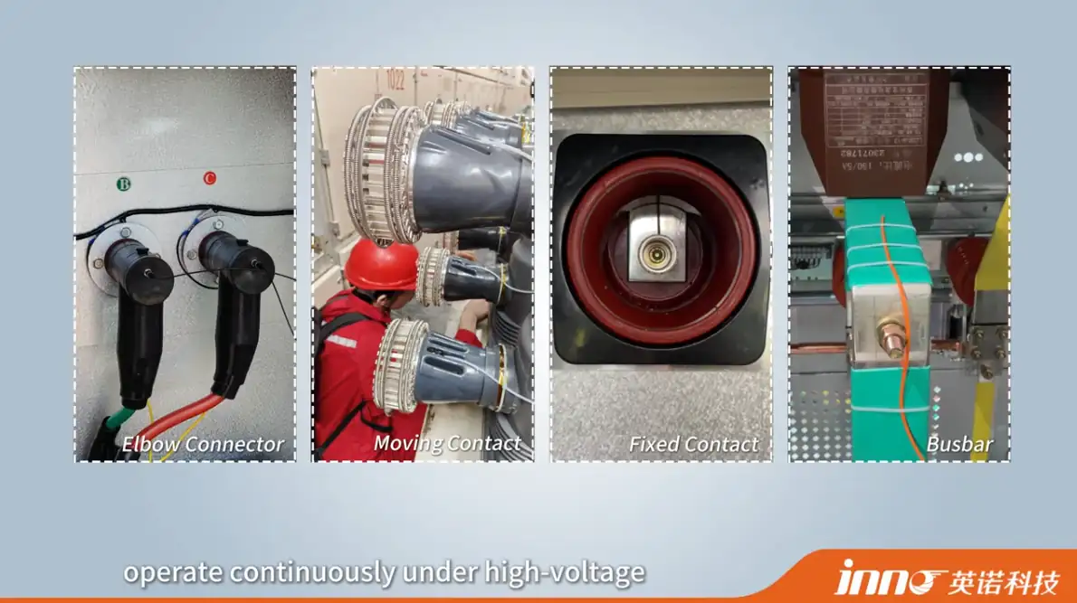
Switchgear monitoring focuses on busbar joints, contacts and terminations. These points are energized and sit in limited space, so probes must fit available clearances and routing out of the compartment needs planning. See switchgear temperature monitoring.
Motors and Generators
Motor and generator monitoring covers windings and selected stator points. Strong electromagnetic fields affect conductive sensor leads, which makes sensor routing a design question. Bearing-related monitoring may use other technologies better suited to that location. See motor and generator temperature monitoring.
High-Voltage Testing
High-voltage testing places an energized test object near measurement equipment. Electrical isolation at the sensing point and defined point measurement allow temperature recording at chosen locations during the test. See high-voltage temperature monitoring.
RF and Microwave Equipment
RF and microwave equipment exposes conductive probes and leads to strong fields. Non-conductive measurement and careful probe routing reduce interaction with the field. See industrial microwave temperature monitoring.
Industrial and Laboratory Equipment
Test benches, R&D setups and laboratory equipment often need multi-point systems, frequently combined with high-voltage, EMI or electrical isolation requirements. Flexible probe placement and channel count usually matter more than a fixed installation layout.
When Fiber Optic Thermal Monitoring Is the Better Fit
Fiber optic thermal monitoring deserves consideration when one or more of these conditions apply:
- The measurement point is at high voltage
- Strong EMI is present
- RF or microwave fields are present
- Strong magnetic fields are present
- Electrical isolation is required
- The point is embedded or internal
- Conductive wiring at the measurement point is undesirable
RTD, thermocouple and infrared methods remain simpler, more economical and often more suitable in ordinary industrial environments. Where points are accessible, grounded and free of strong fields, conventional sensors usually meet the requirement with less complexity.
Fiber optic point sensing adds value when the conditions above apply, and it remains point sensing: each probe measures one location chosen in advance. Further reading is available on fiber optic temperature monitoring systems and fiber optic temperature measurement.
Thermal Monitoring System Specification Table
Information Required for Thermal Monitoring System Selection
| Parameter | What to Define | Why It Matters |
|---|---|---|
| Equipment type | Transformer, switchgear, motor, test object or process equipment | Sets mounting method, environment and likely sensor form |
| Measurement point | Exact location, surface or internal | Determines probe type, installation method and what the reading represents |
| Number of points | Total points plus spare points | Drives channel count and instrument choice |
| Temperature range | Normal operating range and expected abnormal or test limits | Limits sensor and instrument options |
| Required accuracy | Sensor accuracy and overall system accuracy | Affects sensor technology and calibration |
| Required response | Acceptable delay in detecting a temperature change | Depends on probe structure, thermal contact and instrument update behavior |
| Electrical voltage | Voltage level at or near the point | Determines isolation needs |
| EMI / RF / magnetic environment | Field sources, strength and proximity to leads | Decides whether conductive sensors and wiring are acceptable |
| Probe installation space | Available volume, mounting surface and access | Constrains probe diameter and form |
| Cable / fiber routing | Path, bends, penetrations and exposure | Affects feasibility and signal quality |
| Distance to monitoring instrument | Run length from point to instrument | Defines cable or fiber length |
| Channel count | Required channels per instrument | Fixes instrument configuration |
| Alarm requirements | Number of alarm levels, output type and response | Defines instrument functions |
| Communication interface | RS485, Modbus-RTU or another required interface | Must match the plant system |
| PLC / SCADA integration | Target system, data points to expose and polling needs | Defines register mapping and commissioning scope |
| New installation or retrofit | Whether equipment is new or in service | Affects access, shutdown windows and mounting options |
Example Fiber Optic Monitoring Parameters
Typical values depend on probe and instrument configuration.
| Parameter | Typical INNO Configuration |
|---|---|
| Temperature Range | −40 °C to +260 °C |
| Accuracy | ±0.5 to ±1 °C depending on configuration |
| Resolution | 0.1 °C |
| Response Time | Typically <1 s for standard configurations |
| Probe Diameter | Approximately 2–3 mm depending on structure |
| Fiber Length | Configurable |
| Measurement Principle | Fluorescence decay time |
| Measurement Type | Point sensing |
| Channels | Single or multi-channel configurations |
| Communication | RS485 / Modbus-RTU on applicable monitoring instruments |
These values describe typical fluorescence-based configurations and should not be treated as universal specifications for every INNO product.
Common Thermal Monitoring System Selection Mistakes
Choosing the Sensor Before Defining the Measurement Point
Sensor type follows from location, temperature, voltage and field conditions. Selecting hardware first often leads to a probe that cannot be mounted where the measurement is needed.
Confusing Surface Temperature with Internal Temperature
Surface readings and internal readings differ, especially under load and in insulated equipment. Thermal imaging reports surface conditions, and embedded points require sensors placed inside.
Treating Resolution as Accuracy
Fine display resolution can make a reading look more reliable than it is. Specify accuracy for the sensor and the full chain, and check installation conditions as well.
Ignoring Cable or Fiber Routing
Routing paths, bends, penetrations and distance to the instrument can decide whether a design is practical. Conductive leads in strong fields need extra review.
Selecting Too Few Monitoring Channels
Channel counts sized exactly to the initial point list leave no room for added points during commissioning. Spare channels cost less than a second instrument.
Assuming Every System Supports the Same Communication Interface
Interfaces such as RS485 and Modbus-RTU depend on the selected instrument and configuration. Confirm the interface and data points against the PLC or SCADA requirements before ordering.
Defining the Right Thermal Monitoring Architecture
Selecting a thermal monitoring system begins with the measurement point, then moves to sensor technology, continuous or periodic monitoring, number of points, temperature range and electrical environment. Accuracy, response, alarm behavior, communication and PLC or SCADA integration complete the specification.
No single thermal monitoring method is suitable for every industrial application. Conventional sensors remain suitable for many industrial environments. Fiber optic point sensing becomes especially useful where electrical isolation, high voltage, strong EMI, RF, magnetic fields or embedded measurement points influence sensor selection.
Project parameters such as point count, temperature range, routing and communication needs can be sent to contact INNO engineering for configuration review.