
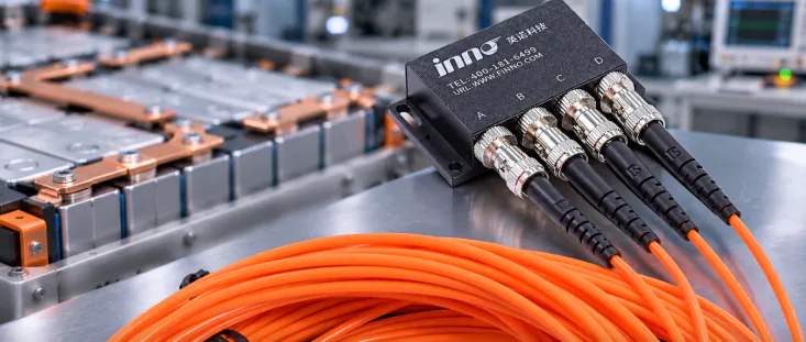
- Measure EV battery pack temperature by placing sensors on representative cell surfaces, electrode tabs or busbar joints, and cooling plates.
- Connect each sensor to a labeled channel and record temperature alongside current, voltage, and test conditions during charging and discharging.
- Compare readings across the selected points to see how temperature varies through the pack and how effectively heat is removed.
- For electrically isolated, EMI-immune measurements at selected points, use fluorescent fiber optic probes with a compatible multi-channel instrument.
Where Should Battery Pack Temperature Be Measured?
Start with the locations that can explain how heat is generated and removed in the pack. A planned set of measurement points makes it easier to compare cells, connections, and cooling performance during the same test.
Battery Cell Surfaces
Measure representative cells during charge, discharge, and thermal-management tests. Include cells in different positions in the module so the data shows how placement and cooling conditions affect temperature.
Electrode Tabs and Busbar Connections
Tabs and busbar joints carry current between cells and modules. Monitoring selected connections alongside cell surfaces gives engineers a clearer picture of temperature distribution through the electrical path.
Cooling Plates and Module Surfaces
Measurements near cooling plates help show how evenly heat is removed. Compare these readings with nearby cell temperatures when tuning a cooling strategy or reviewing a module design.
Which Temperature Sensors Are Used in EV Battery Packs?
Battery programs use different sensors at different stages. NTC thermistors are widely used by battery management systems. Development teams may also use thermocouples, infrared cameras, and fiber optic point sensors to answer specific test questions.
| Sensor type | Common use | What it helps you measure |
|---|---|---|
| NTC thermistor | Battery management | Routine temperature feedback at installed points |
| Thermocouple | Development and laboratory testing | Temperature changes at selected test locations |
| Infrared camera | Thermal surveys | A visual overview of accessible surfaces |
| Fluorescent fiber optic probe | Electrical and thermal testing | Isolated point measurements in electrically demanding test environments |
For a test campaign, the right combination depends on the question being studied. Fiber optic probes are especially useful when engineers want isolated temperature readings at several selected points in a high-voltage or high-EMI environment.
How to Measure Battery Temperature Step by Step
- Set the test objective. Decide whether you are evaluating cell uniformity, connection heating, cooling performance, or the full pack response.
- Mark the measurement points. Select representative cells, tabs or busbar joints, and cooling locations. Record each point on a pack diagram.
- Choose the sensor arrangement. Match sensor type, probe construction, temperature range, channel count, and installation method to the test plan.
- Install and label each probe. Follow the battery and test-system procedures, then label the probe and its corresponding channel clearly.
- Check the setup and collect data. Confirm channel labels and readings, then record temperature together with current, voltage, and operating conditions.
For example, a six-point test can track four representative cell surfaces, one busbar connection, and one cooling-plate location at the same time. A multi-channel instrument keeps the readings together for comparison throughout the test.
What Can Temperature Monitoring Show During Battery Testing?
Temperature data helps teams see how the pack responds under different operating conditions. Compare measurements during charge, discharge, and cooling changes to identify patterns between cells, electrical connections, and heat-removal surfaces.
For instance, if most monitored cells reach 35°C while a selected connection reaches 48°C under the same test conditions, engineers have a useful lead for reviewing that connection and the surrounding design. These figures are an illustration, not a general alarm threshold.
Review the readings with current, voltage, cooling settings, and the test procedure. The combined record helps teams compare prototypes, validate thermal designs, and document results across repeated test cycles.
Why Use Fiber Optic Temperature Sensors for EV Battery Testing?
Fluorescent fiber optic probes measure temperature at a defined point using an optical sensing tip. Their non-conductive sensing path provides electrical isolation, and the optical measurement is immune to electromagnetic interference—useful characteristics around battery modules, power connections, and high-current test equipment.
Small probe tips can be arranged at selected locations where engineers want a direct temperature reading. With a multi-channel instrument, several points can be monitored together, making it easier to compare cells, busbar connections, and cooling components during one test.
INNO supplies fluorescent fiber optic temperature probes and multi-channel instruments for configured point measurements. A typical setup combines probes, fiber connections, a monitoring host, and recording software.
Depending on the instrument configuration, readings can be displayed locally or sent to a data acquisition system through RS485 Modbus RTU. See the fiber optic temperature monitoring systems for available configurations.
How Do You Plan a Battery Temperature Measurement System?
Share the battery layout and test objective with the measurement-system supplier. This makes it possible to match the probe, channel count, fiber route, and data interface to the workbench and test procedure.
- Battery format, module layout, and the locations to monitor
- Expected temperature range and test conditions
- Number of points to record at the same time
- Probe mounting details and approximate fiber route
- Display, logging, alarm, or data acquisition requirements
These details help define a measurement setup that fits the pack and produces data the engineering team can use.
Frequently Asked Questions
Which sensor is suitable for EV battery temperature testing?
It depends on the test. NTC thermistors are common in battery management systems. Fiber optic probes are a strong option for development and laboratory work that calls for electrically isolated, EMI-immune measurements at selected points.
Where should temperature probes be placed on a battery pack?
Typical points include representative cell surfaces, electrode tabs, busbar connections, and cooling plates. The test objective and pack design guide the final locations.
Can several battery points be measured at the same time?
Yes. A multi-channel monitoring instrument can read compatible probes at multiple defined points together. Choose the channel count to match the test layout.
How does fiber optic sensing help in battery tests?
The optical sensing path is non-conductive and immune to electromagnetic interference. This supports isolated point temperature measurements around electrical equipment and high-current test setups.
What information is useful when specifying a system?
Provide the battery configuration, measurement-point diagram, expected temperature range, number of simultaneous channels, probe mounting details, and required data interface. Contact INNO to review a suitable probe and instrument configuration.