
- Semiconductor temperature measurement starts with the physical target: wafer, device junction, package, fixture, heater or chamber component.
- Equipment temperature does not automatically represent wafer temperature or the temperature inside a semiconductor device.
- Thermocouples and RTDs suit many accessible contact measurements; infrared instruments measure visible surfaces without contact.
- RF fields, electrical potential and grounding constraints can make conductive sensor wiring difficult to use reliably.
- Fluorescence fiber optic sensing provides electrically isolated point measurement with high resistance to electromagnetic interference.
- Each fluorescence probe measures one defined physical location; additional locations require additional probes and measurement channels.
Process equipment often needs temperature feedback from locations that are difficult to reach during operation. Heater assemblies, fixtures and chamber components may sit near RF power, moving mechanisms or electrically energized parts. Sensor placement and the signal path must suit those conditions as well as the required temperature range.
Reliable measurements also depend on thermal contact. A sensor attached to a mounting bracket can respond differently from the component it supports. Establish which temperature matters to the process and whether the intended installation can measure it directly.
What Does Semiconductor Temperature Measurement Refer To?
Junction temperature concerns the active region inside a semiconductor device. Wafer temperature concerns the substrate during processing. Package, fixture and chamber measurements describe other parts of the thermal system. Although these temperatures influence one another, they are not interchangeable.
For example, a heater sensor can support temperature control without proving that every wafer location has reached the same temperature. Contact resistance, gas conditions, radiation and transient heating can produce differences between the heater, support and workpiece. Establish the relationship experimentally when one measurement is used to estimate another.
| Measurement Target | Typical Measurement Need | Common Method | Fiber Optic Relevance |
|---|---|---|---|
| Device junction | Internal operating temperature | Electrical temperature-sensitive parameters or integrated sensing | External probe readings do not directly establish junction temperature |
| Wafer | Process temperature and spatial uniformity | Instrumented wafers or suitable optical methods | Accessible local points only; not inherently full-wafer mapping |
| Package or module | Case and interface temperature | Contact sensors or infrared measurement | Useful where electrical isolation is required |
| Fixture or heater | Control feedback and development measurements | Thermocouple, RTD or embedded probe | Applicable to defined points near RF or electrical potential |
| Chamber component | Wall, support or feedthrough temperature | Installed contact sensor or optical measurement | Requires compatible materials, mounting and vacuum feedthroughs |
| Equipment test point | Component heating during operation | Method selected for accessibility and environment | Suitable for isolated, independently monitored locations |
Why RF and Process Equipment Can Require Different Temperature Sensors
Conductive sensor leads can pick up unwanted signals, form ground loops or create an electrical connection across a potential difference. In RF equipment, lead geometry and routing can also affect coupling. Shielding, filtering, grounding and instrument isolation therefore belong in the measurement design, not just the final troubleshooting stage.
During RF and microwave heating measurements, a temperature change should be distinguished from an electrical disturbance. Comparing readings with RF power enabled and disabled, while accounting for actual heating, can help identify unstable measurement behavior.
Measurements in strong electromagnetic fields require attention to the complete signal path. Optical transmission removes the conductive sensor lead from that path, but the monitoring instrument still needs suitable power, installation and communications practices.
Electrical isolation is separate from noise resistance. Where the sensing location is energized, an electrically isolated temperature sensor must be assessed together with clearances, mounting materials and applicable safety requirements. Infrared measurement avoids contact but needs a usable optical path; an enclosed or embedded location may not provide one.
Semiconductor Temperature Measurement Methods
Thermocouples
Thermocouples provide practical contact measurement across many heater and equipment locations. Small junctions fit constrained installations, and suitable constructions cover a wide range of operating conditions. Measurement accuracy depends on the complete assembly, cold-junction compensation, wiring and calibration.
Metal leads require careful routing near RF sources or energized components. Properly designed thermocouple installations remain useful in process equipment; suitability should be established at the actual measurement location.
RTD / PT100
RTDs suit stable contact measurements where probe construction and temperature range match the equipment. Lead resistance, excitation current, self-heating and the choice of two-, three- or four-wire connection affect results. Mechanical attachment and thermal contact determine how closely the reading follows the component.
Infrared Measurement
Infrared instruments measure surface radiation without attaching a probe. They can observe moving or inaccessible surfaces when an optical path is available. Emissivity, reflections, viewing angle, spot size and window transmission influence the indicated temperature. Surface coatings or process deposits can change these conditions between runs.
Fluorescence Fiber Optic Sensors
Fluorescence probes use a temperature-sensitive sensing material and an optical connection to the monitoring instrument. They suit contact measurements where electrical isolation or resistance to RF-related interference is valuable. Probe access, attachment, material compatibility and fiber routing remain necessary installation requirements.
| Method | Contact Type | Electrical Conductors at Sensing Point | Line-of-Sight Required | Strong RF / EMI Suitability | Main Limitation |
|---|---|---|---|---|---|
| Thermocouple | Contact | Yes | No | Requires appropriate wiring and interference control | Electrical pickup, grounding and junction installation |
| RTD / PT100 | Contact | Yes | No | Requires appropriate circuit and installation design | Lead effects, self-heating and electrical connection |
| Infrared | Non-contact | Not required at the target | Yes | Instrument and viewing arrangement dependent | Emissivity, reflections and optical access |
| Fluorescence fiber optic | Contact point measurement | No conductive signal lead; construction must be verified | No | High resistance to electromagnetic interference | Physical probe access and installation compatibility |
How Fluorescence Lifetime Temperature Measurement Works
Excitation light travels from the instrument through the fiber to fluorescent material at the probe tip. After excitation ends, the material continues emitting light for a short period. Its fluorescence decay time changes with temperature.
Returning light reaches a photodetector in the instrument. Readout electronics convert the optical response into an electrical waveform, and the measurement algorithm extracts a lifetime from the decay. Calibration then relates that lifetime to temperature. The resulting value can be displayed, recorded or transmitted to an equipment controller.
Lifetime is not simply the brightness of the returned signal. Nevertheless, sufficient signal quality is needed to estimate the decay reliably. Optical losses, connector condition, background light, detector behavior and electronic noise can affect the usable waveform. Calibration cannot compensate for every installation fault or an inadequate signal.
Measurement performance therefore belongs to the complete system: sensing material, optical path, photodetection, readout electronics, lifetime extraction and calibration. A 2026 Scientific Reports study, Chip-based high-precision fluorescent fiber-optic temperature sensor, showed that readout noise and fluorescence-lifetime extraction can materially influence performance in a research prototype.
For equipment integration, fluorescence-based temperature sensing should be specified with the intended probe and instrument combination. Display resolution does not establish accuracy, and an instrument update interval does not establish installed thermal response. Probe dimensions, attachment and the surrounding medium influence how quickly a temperature change reaches the sensing material.
Where Fiber Optic Sensors Fit in Semiconductor Equipment
Defined measurement points in RF heating assemblies, electrically isolated fixtures and heater structures can benefit from optical signal transmission. Plasma-related equipment may also contain suitable locations, but suitability near a plasma does not establish that a probe can withstand direct plasma exposure.
A semiconductor equipment temperature monitoring system must match the exposure at each location. Evaluate operating temperature, pressure, process gases, chemical contact, contamination limits and mechanical movement. Probe jackets, adhesives and feedthrough components need compatibility checks rather than assumptions based on the fiber alone.
Vacuum installations add sealing and material requirements. In vacuum chamber measurement, the probe route must pass through a suitable feedthrough without compromising the chamber seal. Protect the fiber from pinching, unsupported movement and bends tighter than the specified installation limit. Keep connectors accessible for inspection and service.
INNO fluorescence sensing is point sensing. One probe measures one defined physical point; multiple locations require multiple probes and channels. It is not distributed temperature sensing, automatic temperature mapping or a dedicated TC wafer, RTD wafer or wireless wafer sensor. Placement must follow the equipment design and the thermal question being investigated.
Development equipment can use multi-point temperature monitoring to compare selected fixture, heater and support locations. Record a channel-to-location map and retain it with the test data. Channel count alone does not define measurement coverage, and readings from several locations do not establish the temperature between them.
Typical INNO Fluorescence Fiber Optic Parameters
Typical values depend on the probe and monitoring-system configuration. Confirm the selected assembly against the equipment requirements; the values below are not a qualification for every vacuum, plasma or high-voltage installation.
| Parameter | Typical Configuration |
|---|---|
| Measurement principle | Fluorescence decay time |
| Temperature range | −40 °C to +260 °C |
| Accuracy | ±0.5 °C to ±1 °C depending on configuration |
| Resolution | 0.1 °C |
| Response | <1 s for standard configurations |
| Probe diameter | 2–3 mm, configurable |
| Fiber length | Configurable |
| Electrical insulation | >100 kV for applicable configurations |
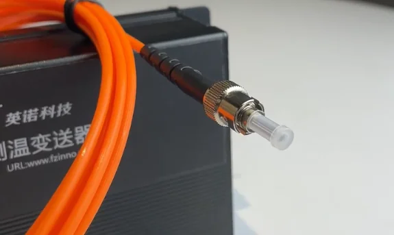
| Connector | ST |
| Channels | Single-channel and multi-channel |
| Communication | RS485 / Modbus RTU for applicable instruments |
Selecting the Measurement Method
Start with the target and the decision the measurement supports. Process control, overtemperature protection and development testing may need different locations and response characteristics. Specify whether the required value is a surface, embedded component or workpiece temperature, and identify any inference between the measured point and the controlled process.
Next, establish whether contact is possible. If a probe can be installed, assess its thermal coupling and whether it changes the assembly being tested. If contact is unacceptable, evaluate optical access and surface properties before selecting infrared measurement. Neither approach removes the need to validate the installed reading.
Assess RF exposure, electrical potential and grounding constraints before selecting the signal path. Where a conventional RTD or thermocouple already meets the measurement and safety requirements, there is no need to use fiber optic sensing solely for its technology. Fluorescence fiber optic temperature sensors are useful when their isolation or interference resistance solves a defined installation problem.
Specify accuracy, resolution and response separately. Required accuracy should reflect the acceptable decision error, including mounting effects and calibration uncertainty. A fast display cannot correct slow thermal contact. Check performance during the temperature changes and equipment operating states that matter, rather than only at a stable room-temperature condition.
Finally, define the number of independent points, installed fiber routes and controller interface. PLC / SCADA integration requires a documented register map, units, update behavior and handling of disconnected probes or invalid readings. Confirm which alarms are informational and which participate in a separately validated protection function.
Matching the Sensor to the Semiconductor Equipment
The measurement target comes first. Conventional sensors remain appropriate for many equipment locations, while fluorescence point sensing addresses installations where electrical isolation, RF resistance or access to a defined embedded point changes the sensor requirements.
System configuration should follow the actual locations, thermal conditions, fiber routes and controller interfaces. Projects involving defined RF, high-voltage or electrically isolated measurement points can be discussed with the INNO engineering team using the intended measurement locations, temperature range and channel requirements.